The ULP is a low-power coprocessor (Ultra Low Power) integrated into the ESP32 MCU. It's a very small processor that can run independently from the main cores and that has access to the GPIOs, some peripheral and an I²C controller.
The ULP is also able to run when the ESP32 is is deep-sleep mode. In this mode, nearly the whole MCU is powered-off, except the RTC domain, in which the ULP is built. It is also able to wake the ESP32 up.
A possible application of the ULP is to acquire temperature while the ESP32 is in deep-sleep and to wake it up once it reaches a specified threshold.
Programming the ULP seems very interesting, but even if the documentation from Espressif is very complete, I couldn't find a simple and easy example to learn how to use it.
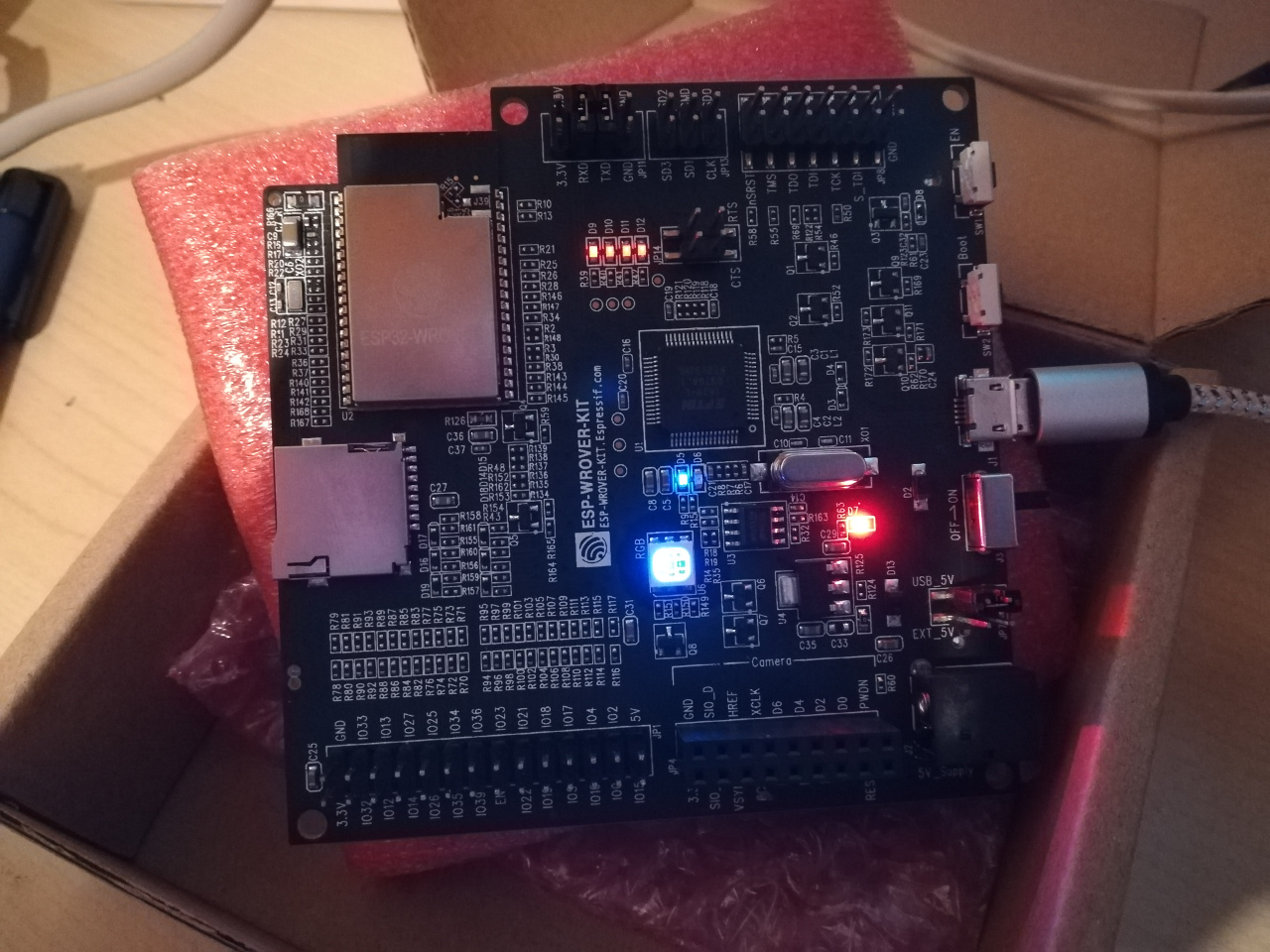
Here is then in details an ultra simple exemple : the traditional blink, which blinks 2 LEDs on the WROVER-KIT V3.
The example I'll explain here consists in blinking 2 LEDs (the blue and the green ones from the ESP32-WROVER-KIT V3). The 1st one is driven by the main core, the second one by the ULP.
Installing the ULP toolchain
The installation is documented in the official documentation.
The project & CMake
Oh, by the way : you program the ULP in its assembly language. There's obviously no C compiler available!
We'll start by creating a file with the extension .S in a subdirectory of the project. I called it ulp/main-ulp-blink.S.
Next, we'll edit the file CMakeLists.txt of the main component to add the code for the ULP:
set(COMPONENT_SRCS "ulp_blink.c")
set(COMPONENT_ADD_INCLUDEDIRS "")
register_component()

# Ajouter les lignes suivantes pour compiler le code de l'ULP
set(ULP_APP_NAME ulp_${COMPONENT_NAME})
set(ULP_S_SOURCES ulp/main-ulp-blink.S)
set(ULP_EXP_DEP_SRCS "main-ulp-blink.c")
include(${IDF_PATH}/components/ulp/component_ulp_common.cmake)
The "application" program
#include <stdio.h>
#include "freertos/FreeRTOS.h"
#include "freertos/task.h"
#include "esp_system.h"
#include "esp_spi_flash.h"
#include "driver/gpio.h"
#include "esp32/ulp.h"
#include "ulp_main.h"
#include "driver/rtc_io.h"

extern const uint8_t bin_start[] asm("_binary_ulp_main_bin_start");
extern const uint8_t bin_end[]   asm("_binary_ulp_main_bin_end");

void app_main() {
  /* Init GPIO 4 (blue), which will be driven by the main core */
  gpio_config_t io_conf;
  io_conf.intr_type = GPIO_PIN_INTR_DISABLE;
  io_conf.mode = GPIO_MODE_OUTPUT;
  io_conf.pin_bit_mask = GPIO_SEL_4;
  io_conf.pull_down_en = 0;
  io_conf.pull_up_en = 0;
  gpio_config(&io_conf);

  /* Init GPIO2 (RTC_GPIO 12, green) which will be driven by ULP */
  rtc_gpio_init(2);
  rtc_gpio_set_direction(2, RTC_GPIO_MODE_OUTPUT_ONLY);
  rtc_gpio_set_level(2,0);

  vTaskDelay(1000/portTICK_PERIOD_MS);

  /* Start ULP program */
  ESP_ERROR_CHECK( ulp_load_binary(0, bin_start, (bin_end - bin_start) / sizeof(uint32_t)));
  ESP_ERROR_CHECK( ulp_run(&ulp_entry - RTC_SLOW_MEM) );

  bool s = false;
  for (;;) {
    s = !s;
    gpio_set_level(4, (s ? 1 : 0));
    vTaskDelay(1000/portTICK_PERIOD_MS);
  }
}
This program is voluntarily very simple. It starts by initializing the GPIOs : GPIO4 for the blue LED, GPIO2/RTC_GPIO12 for the green LED. Not that we use rtc method for the green LED, as it'll be driven by the ULP.
Next, it programs the ULP and start it, and then, enters in an infinite loop. This loop powers-ON/OFF the blue LED every 1 second. In the meantime, the ULP takes care of the green LED.
The ULP program
For informations, here is the documentation of the assembly language. This document is very useful if you want to understand and write your own programs.
#include "soc/rtc_cntl_reg.h"
#include "soc/soc_ulp.h"
#include "soc/rtc_io_reg.h"

    .bss

    .text
	.global entry
entry:
    .global loop1

loop1:
    WRITE_RTC_REG(RTC_GPIO_OUT_REG,RTC_GPIO_OUT_DATA_S+12,1,1)
    WAIT 65535
    WAIT 65535
    WAIT 65535
    WAIT 65535
    WAIT 65535
    WAIT 65535
    WAIT 65535
    WAIT 65535
    WAIT 65535
    WAIT 65535
    WAIT 65535
    WAIT 65535
    WAIT 65535
    WAIT 65535
    WAIT 65535
    WAIT 65535
    WAIT 65535
    WAIT 65535
    WRITE_RTC_REG(RTC_GPIO_OUT_REG,RTC_GPIO_OUT_DATA_S+12,1,0)
    WAIT 65535
    WAIT 65535
    WAIT 65535
    WAIT 65535
    WAIT 65535
    WAIT 65535
    WAIT 65535
    WAIT 65535
    WAIT 65535
    WAIT 65535
    WAIT 65535
    WAIT 65535
    WAIT 65535
    WAIT 65535
    WAIT 65535
    WAIT 65535
    WAIT 65535
    WAIT 65535

    JUMP loop1
Wow, that's a lot of WAITs... I'll come to it later on :)
The program, written in ULP assembly, start by declaring an empty BSS segment (it contains declaration of variable, but this program is so simple it doesn't even need one). Next comes the TEXT segment which contains the code.
This code writes a 1 on GPIO2/RTC_GPIO12, waits, wait, waits some more, than writes a 0 on this GPIO, waits again, and start again.
Why so much WAITs? The mnemonic WAIT accepts as operand a 16bits (0..65535) value. It's the number of cycles (@8MHZ) we want to wait until the next instruction. If you specify a greater value, the assembler drops them, and only uses the 16 lower bits, and waits for less than you would have expected.
In order to keep the example as simple as possible, I've decided to not write a true loop to wait, and simply add multiple WAITs so that we can see the blinking with our eyes.
The source code of this example is available on my GitHub.