The LoRa backplate for the Pinephone
A few months ago, Pine64 sent me a few prototypes of their new devices from the PineDio range. PineDio is the name of LoRa based devices :
- The PineDio STACK : a development board based on the BL604 RISC-V MCU, equipped with the SX1262 LoRa module
- The PineDio Gateway : a LoRa gateway based on the Pine A64 SBC and the RAK2287 LoRa concentrator
- The PineDio USB adapter : a USB adapter to the Sx1262 LoRa module
- The PineDio LoRa backplate for the Pinephone
I’ve already shared some information about the gateway on this blog and about the USB adapter on the Pine64 wiki .
Now, it’s time to have a look at that LoRa backplate for the Pinephone:
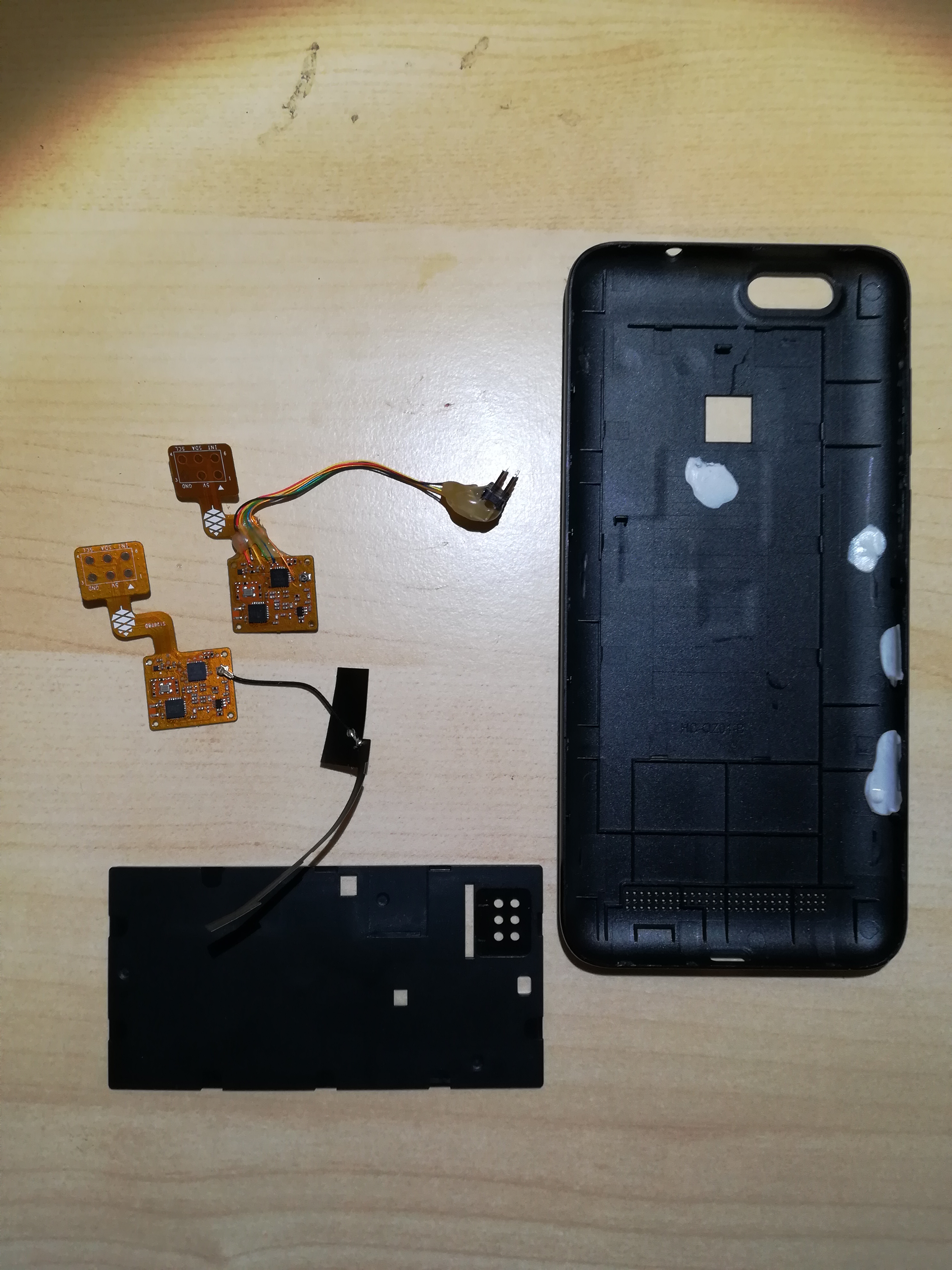
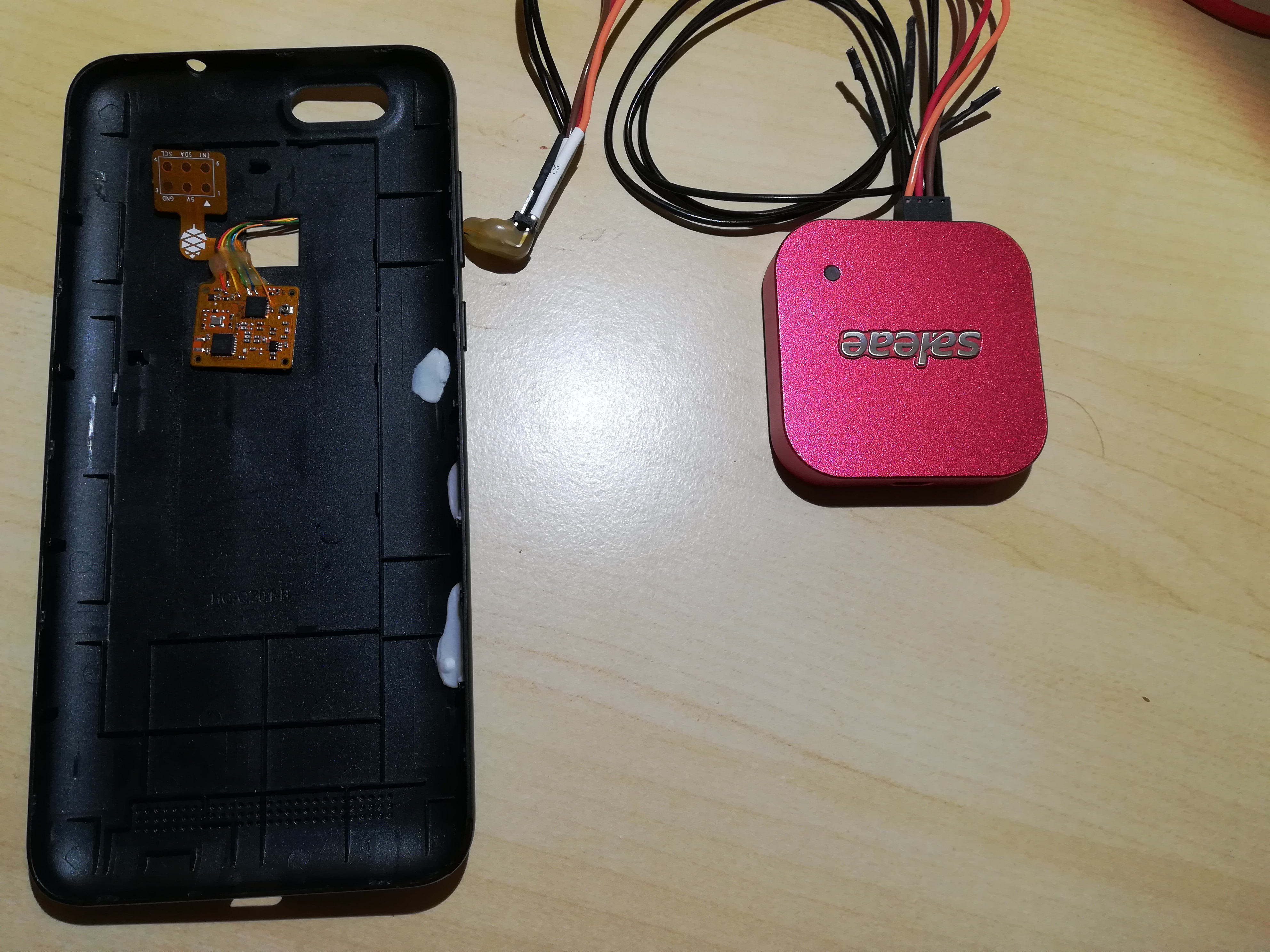
Here’s what I received : 2 small flex PCBs, one with a flex antenna, the second one with soldered wires, the backcover and the plastic plate that maintains the PCB in place.
Let’s have a closer look to the PCBs:
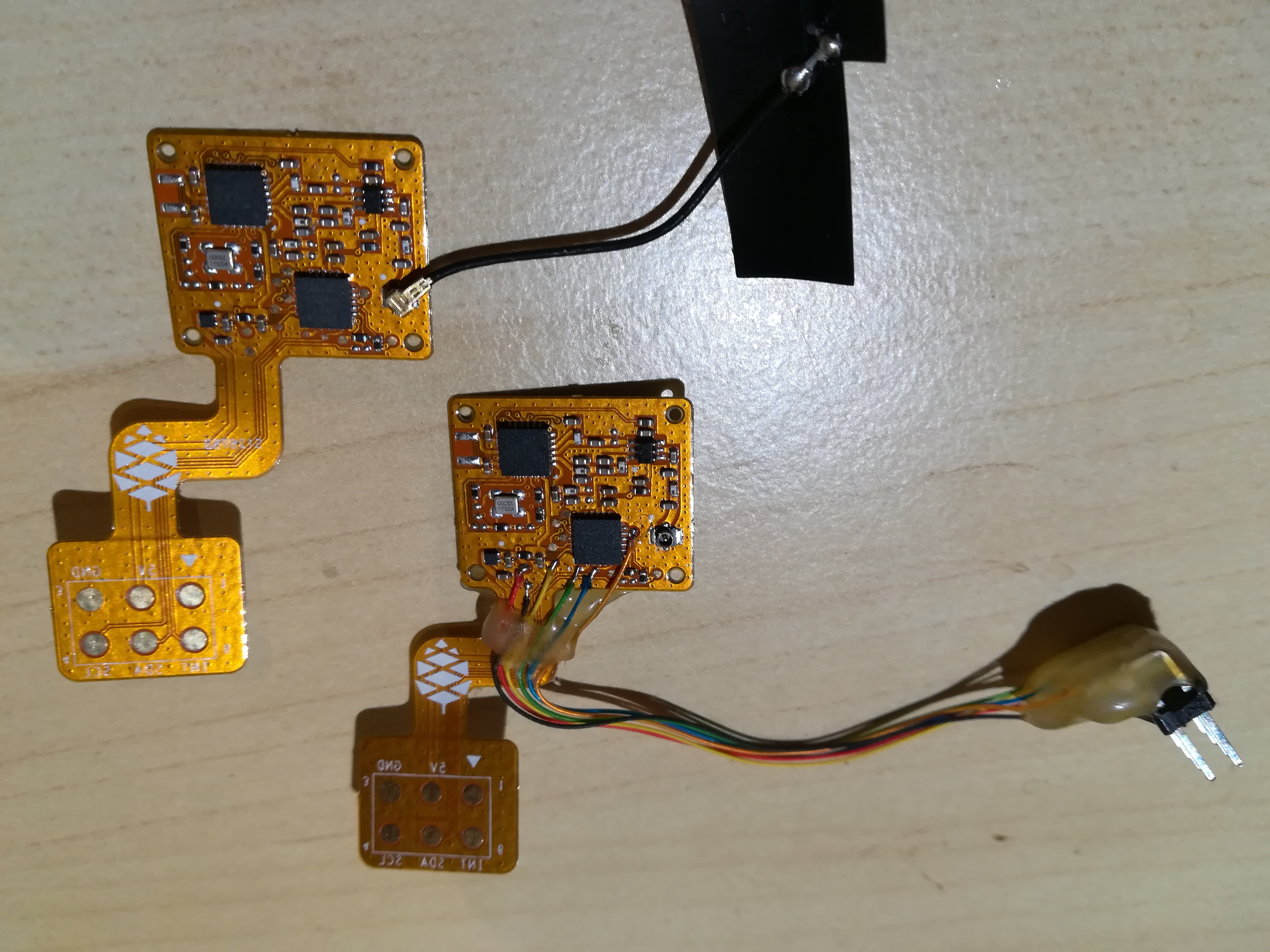
There are 2 main chips:
- on the top : the SX1262 LoRa module
- on the bottom : an ATTiny84 MCU
According to the schematics of the board , the ATTiny84 is needed to convert from the I²C bus coming from the PinePhone to an SPI bus needed by the SX1262 module. The wiki points to this repo for the firmware of this “bridge” MCU.
Let’s mount it and see what happens!
Installing the PCB and the antenna into the back cover is not that easy… I used a bit of sticky paste to keep everything in place:
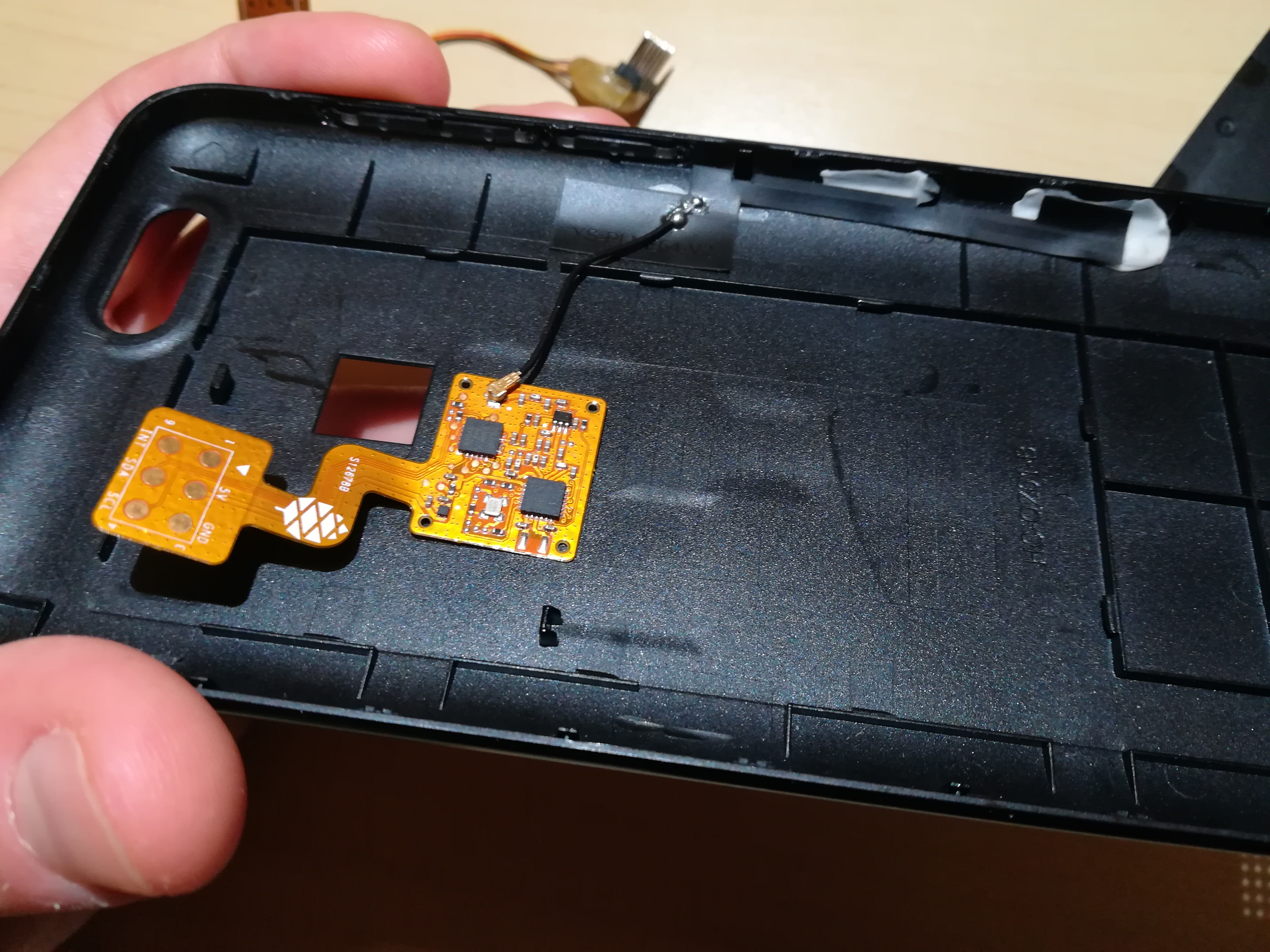
With the plastic cover:
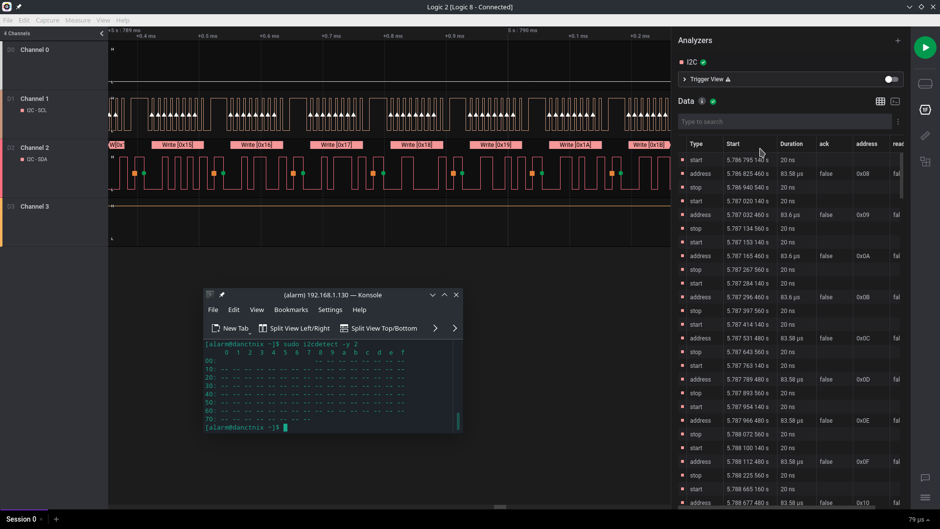
Looks good! Now, let’s boot the Pinephone (I’m running ArchLinux for now), install i2c-tools and run i2cdetect on I2C-2 :
[alarm@danctnix ~]$ sudo i2cdetect -y 2
     0  1  2  3  4  5  6  7  8  9  a  b  c  d  e  f
00:                         -- -- -- -- -- -- -- --
10: -- -- -- -- -- -- -- -- -- -- -- -- -- -- -- --
20: -- -- -- -- -- -- -- -- -- -- -- -- -- -- -- --
30: -- -- -- -- -- -- -- -- -- -- -- -- -- -- -- --
40: -- -- -- -- -- -- -- -- -- -- -- -- -- -- -- --
50: -- -- -- -- -- -- -- -- -- -- -- -- -- -- -- --
60: -- -- -- -- -- -- -- -- -- -- -- -- -- -- -- --
70: -- -- -- -- -- -- -- --
Accoridng to the code of the bridge firmware running on the ATTINY84 , the device should answer to address 0x28 but… there’s nothing. As if the MCU was not flashed with that firmware (or any firmware at all)…
Let have a closer look at the schematics
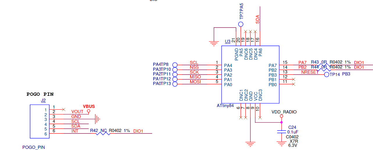
On this picture, we can see the pogo connector from the Pinephone and the ATTiny84. Here’s the pin mapping:
| Pogo pin | Pin on ATTiny84 |
|---|---|
| VOUT | VCC |
| GND | GND |
| I²C SCL | PA4 |
| I²C SDA | PA6 |
| INT | DIO1 |
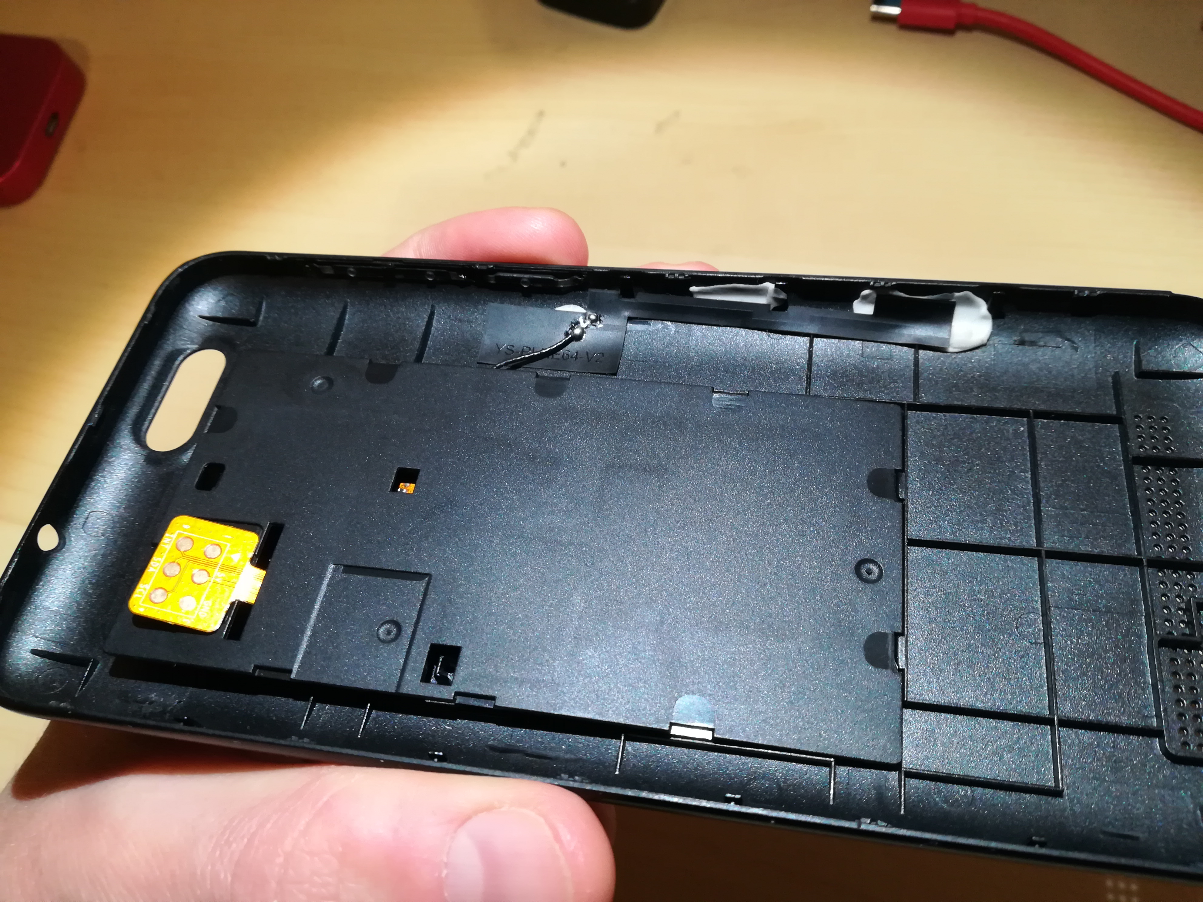
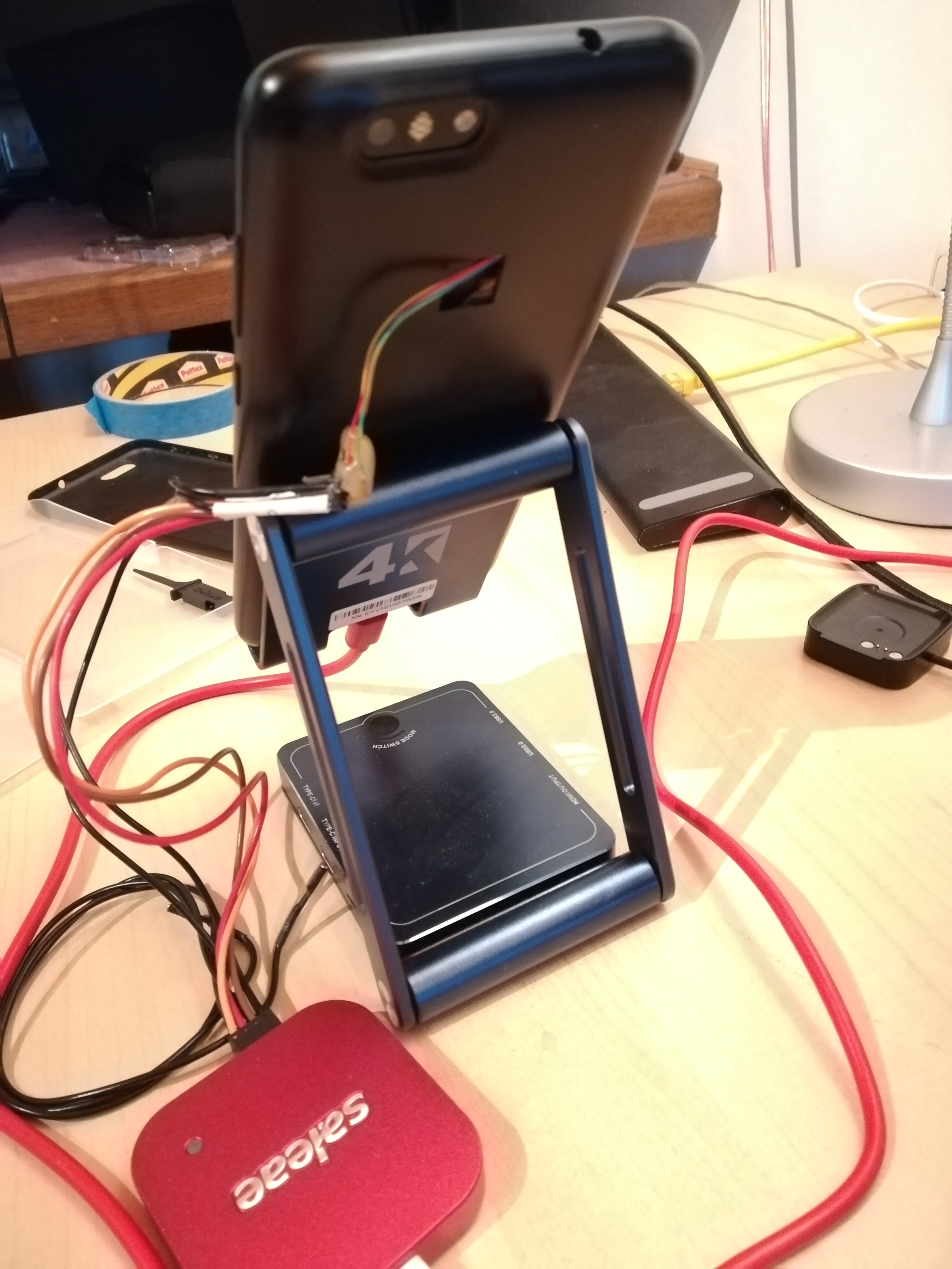
At first, I thought that the 6 soldered wires where in fact connected to those pogo pins. To check this, I installed the second board with the soldered wires into the Pinephone:
I think the backplate was designed for the fingerprint sensor, as it provides a hole on the back. That’s good, I can pass the wires through this hole:
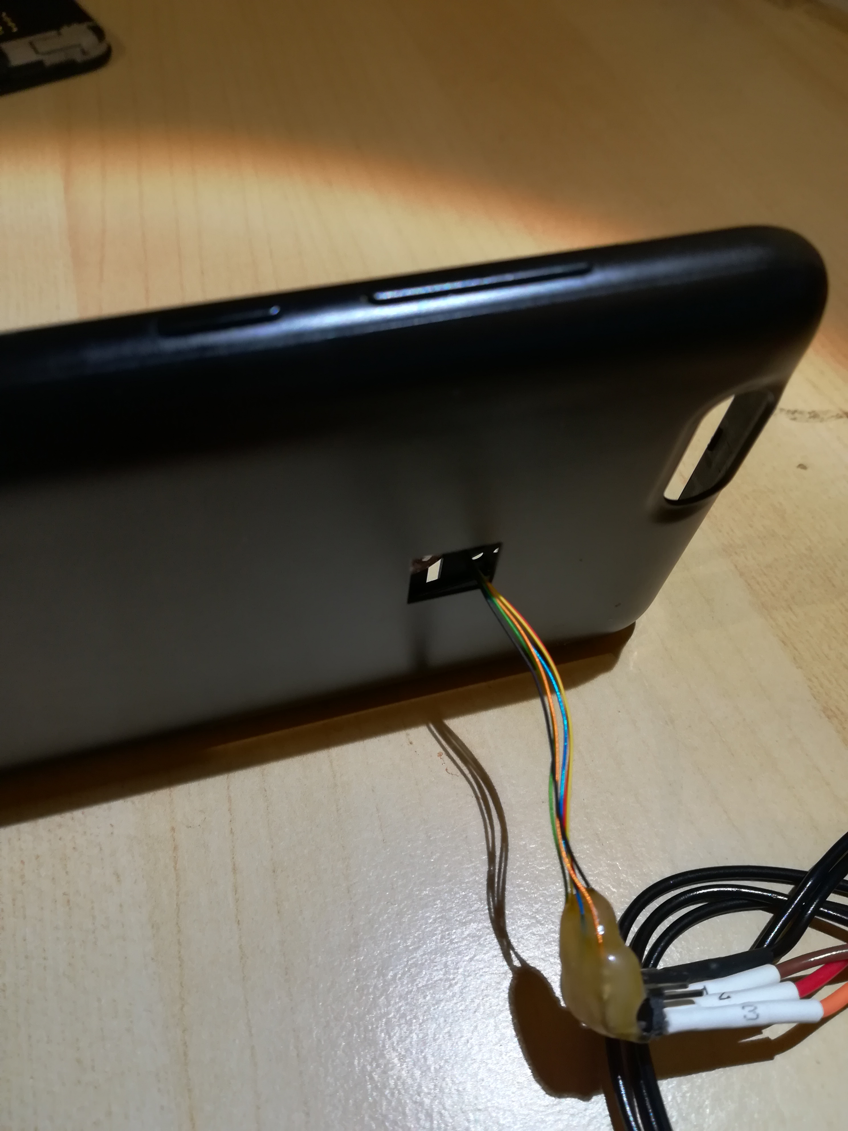
The Pinephone is now running with the logic analyzer connected to those wires:
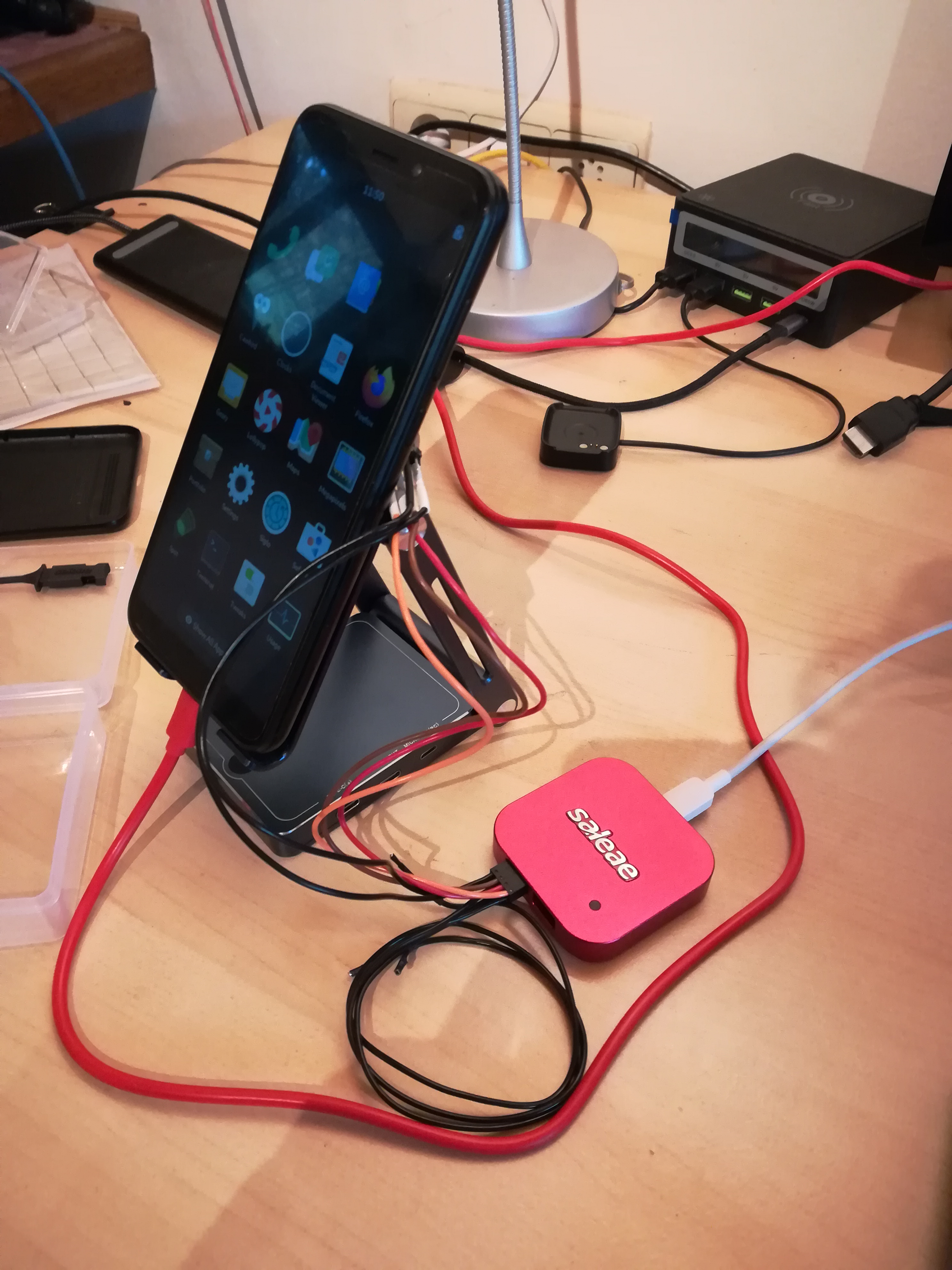
Let’s try i2cdetect again:
So, we have valid I²C signal on 2 of those pins coming from the Pinephone, but no response from the ATTiny84…
Is it… a programming header ?
So, let’s assume the ATTiny84 is not flashed with this bridge firmware, how can I flash it? What if the engineers who designed the board provided me with everything I need to flash it myself? What if those 6 soldered wires were the programming header of the ATTiny?
According to the documentation of the MCU, the ISP (In Situ Programming) is based on SPI and needs 6 pins:
- VCC
- GND
- SPI MOSI
- SPI MISO
- SPI CLOCK
- RESET
I don’t have any info about those wires, but according to their position on the PCB, I can assume the following:
| ATTiny84 Pin | Pogo pin | Programming pin |
|---|---|---|
| VCC | VCC | VCC (red) |
| GND | GND | GND (black) |
| PA4 | I²C SCL | SPI CLOCK (yellow ?) |
| PA5 | - | SPI MISO (green?) |
| PA6 | I²C SDA | SPI MOSI (blue?) |
| PB3 | - | RESET (orange?) |
Ok, it looks consistent! I’ll try to confirm those assumptions with Pine64 before going further.
What’s next
If those assumptions are correct, I’ll need to build the firmware for the ATTiny84 and find a way to flash this firmware to the MCU.
As I don’t have any programming gears from Microchip, I’ll probably have to build my own ISP (based on an ESP8266, ESP32, BL602, RPI or whatever I have on hands), and learn a bit on the toolchain for Microchip MCU, as I have very few experience with them.