In the previous article about the LoRa backplate for the PinePhone , I introduced the devices and tried to understand how it was supposed to work (I received the devices with no instructions at all).
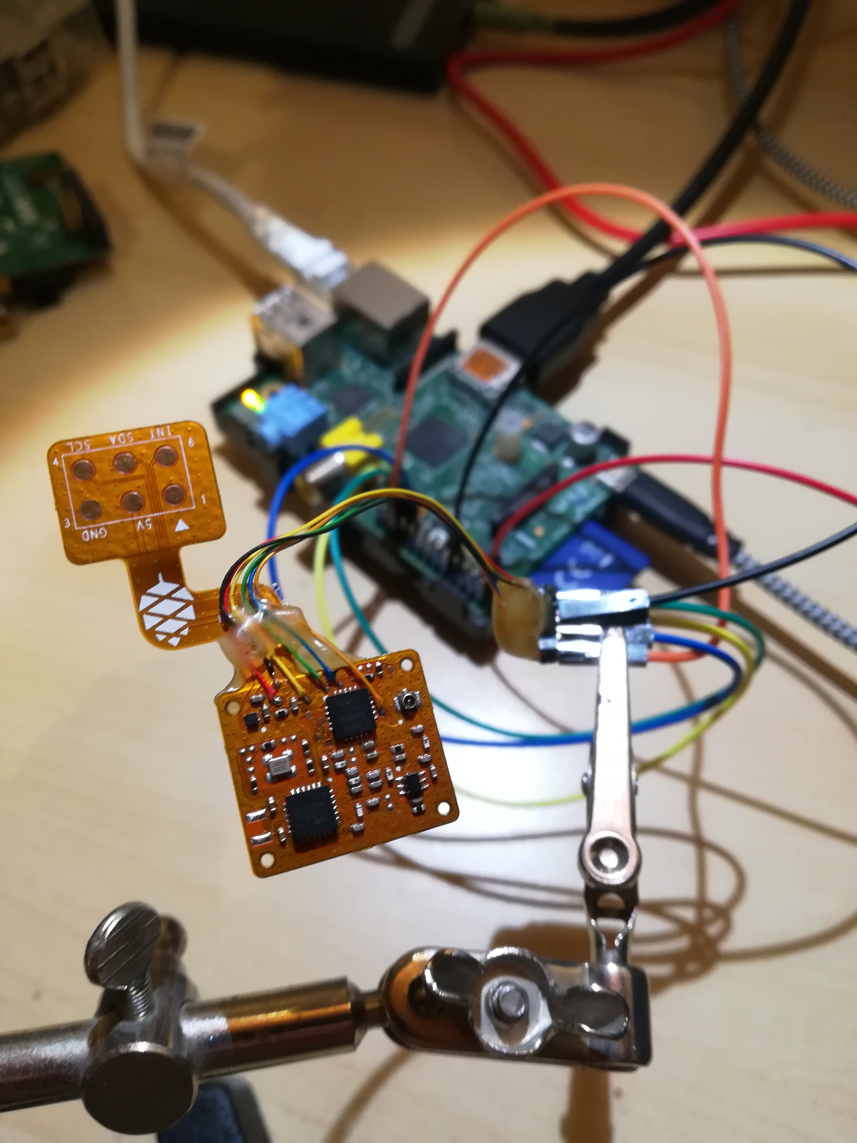
I made a few assumptions regarding the pinout of the pogo pads and of the wires that were soldered on one of the board by looking at the PCB, at the schematics and at the source code of the bridge (I²C <-> SPI) firmware that is linked on the wiki :
Pogo pins:
| Pogo pin | Pin on ATTiny84 |
|---|---|
| VOUT | VCC |
| GND | GND |
| I²C SCL | PA4 |
| I²C SDA | PA6 |
| INT | DIO1 |
Soldered wires (programming header):
| ATTiny84 Pin | Pogo pin | Programming pin |
|---|---|---|
| VCC | VCC | VCC (red) |
| GND | GND | GND (black) |
| PA4 | I²C SCL | SPI CLOCK (yellow) |
| PA5 | - | SPI MISO (green) |
| PA6 | I²C SDA | SPI MOSI (blue) |
| PB3 | - | RESET (orange) |
Those programming pins corresponds to the pins needed to flash the onboard ATtiny84 : power + reset + SPI.
So… Let’s try to flash that thing!
Using a RaspberryPi to flash the MCU
As I said in the previous article, I have very little knowledge of the ATTiny and do not have any hardware specific to AVR MCUs. Fortunately, the firmware is very simple and I could find all the information I need on the internet. ATMEL does provide flashers and debuggers that are designed to work with their MCUs, but they are actually not needed to simply flash a binary into the flash memory of the MCU. They use a very simple protocol on top of an SPI bus, so it should be really easy to build a DIY flasher for the microcontroller.
I’ve seen a lot of article showing how to flash the ATtiny using an Arduino board, but I don’t have any either. And finally, I found this PDF that explains how to set up the RaspberryPi to program the ATtiny84 , awesome! I have a few RaspberryPi on hands, but the only one that is not currently in use is an old RaspberryPi1 with 1 core and 512MB of RAM! It’s at least 10 years old!
Anyway, I know that the RaspberryPi teams does great job maintaining retrocompatibility so… it should just work, right?
And… YES, it does! I simply flashed the last version of the RaspberryPi OS on an SD card (not µSD) and followed the instructions from the PDF.
Wire the programming header on the RPI:
- GND -> black wire
- 3.3v -> red wire
- SPI CLOCK -> yellow wire
- MISO -> green wire
- MOSI -> blue wire
- GPIO25 -> orange wire
Install the AVR toolchain
The AVR toolchain is needed to build the firmware:
sudo apt-get install bison automake autoconf flex git gcc
sudo apt-get install gcc-avr binutils-avr avr-libc
Build AVRDude from sources
This specific version of avrdude is needed because it has the driver needed to flash over the SPI bus of the RaspberryPi.
git clone https://github.com/kcuzner/avrdude
cd avrdude/avrdude
./bootstrap && ./configure && sudo make install
This old RPI1 is very slow, it took quite some time to build… Let’s grab some coffee!
Building the firmware
But first, we need to build the firmware from the sources availables on Github .
git clone https://github.com/zschroeder6212/tiny-i2c-spi
cd tiny-i2c-spi/src
make
Here’s the output:
$ make
avr-gcc -mmcu=attiny84 -Wall -Os -o i2c-spi-bridge.elf main.c USI_TWI_Slave.c SoftSPI.c SoftwareSerial.c
USI_TWI_Slave.c: In function ‘usiTwiTransmitByte’:
USI_TWI_Slave.c:196:13: warning: unused variable ‘tmphead’ [-Wunused-variable]
     uint8_t tmphead;
             ^
SoftwareSerial.c: In function ‘softSerialBegin’:
SoftwareSerial.c:302:27: warning: comparison of constant ‘255’ with boolean expression is always false [-Wbool-compare]
   if ( ! error && ! rxpin == SOFTWARE_SERIAL_RX_DISABLED )
                           ^
SoftwareSerial.c:302:27: warning: logical not is only applied to the left hand side of comparison [-Wlogical-not-parentheses]
avr-objcopy -j .text -j .data -O ihex i2c-spi-bridge.elf i2c-spi-bridge.hex
avr-size --mcu=attiny84 --format=avr i2c-spi-bridge.elf
AVR Memory Usage
----------------
Device: attiny84

Program:    3038 bytes (37.1% Full)
(.text + .data + .bootloader)

Data:        398 bytes (77.7% Full)
(.data + .bss + .noinit)
Check the connection with the ATtiny84
$ sudo avrdude -p t84 -P /dev/spidev0.0 -c linuxspi -b 10000

avrdude: AVR device initialized and ready to accept instructions

Reading | ################################################## | 100% 0.01s

avrdude: Device signature = 0x1e930c

avrdude: safemode: Fuses OK (E:FF, H:DF, L:62)

avrdude done.  Thank you.
Yay! It works!
Let’s flash the firmware
$ sudo avrdude -c linuxspi -P /dev/spidev0.0 -p attiny84 -b 1000 -U flash:w:/home/pi/tiny-i2c-spi/src/i2c-spi-bridge.hex

avrdude: AVR device initialized and ready to accept instructions

Reading | ################################################## | 100% 0.03s

avrdude: Device signature = 0x1e930c
avrdude: NOTE: "flash" memory has been specified, an erase cycle will be performed
         To disable this feature, specify the -D option.
avrdude: erasing chip
avrdude: reading input file "/home/pi/tiny-i2c-spi/src/i2c-spi-bridge.hex"
avrdude: input file /home/pi/tiny-i2c-spi/src/i2c-spi-bridge.hex auto detected as Intel Hex
avrdude: writing flash (3038 bytes):

Writing | ################################################## | 100% 30.67s

avrdude: 3038 bytes of flash written
avrdude: verifying flash memory against /home/pi/tiny-i2c-spi/src/i2c-spi-bridge.hex:
avrdude: load data flash data from input file /home/pi/tiny-i2c-spi/src/i2c-spi-bridge.hex:
avrdude: input file /home/pi/tiny-i2c-spi/src/i2c-spi-bridge.hex auto detected as Intel Hex
avrdude: input file /home/pi/tiny-i2c-spi/src/i2c-spi-bridge.hex contains 3038 bytes
avrdude: reading on-chip flash data:

Reading | ################################################## | 100% 29.89s

avrdude: verifying ...
avrdude: 3038 bytes of flash verified

avrdude: safemode: Fuses OK (E:FF, H:DF, L:62)

avrdude done.  Thank you.
Looks good!
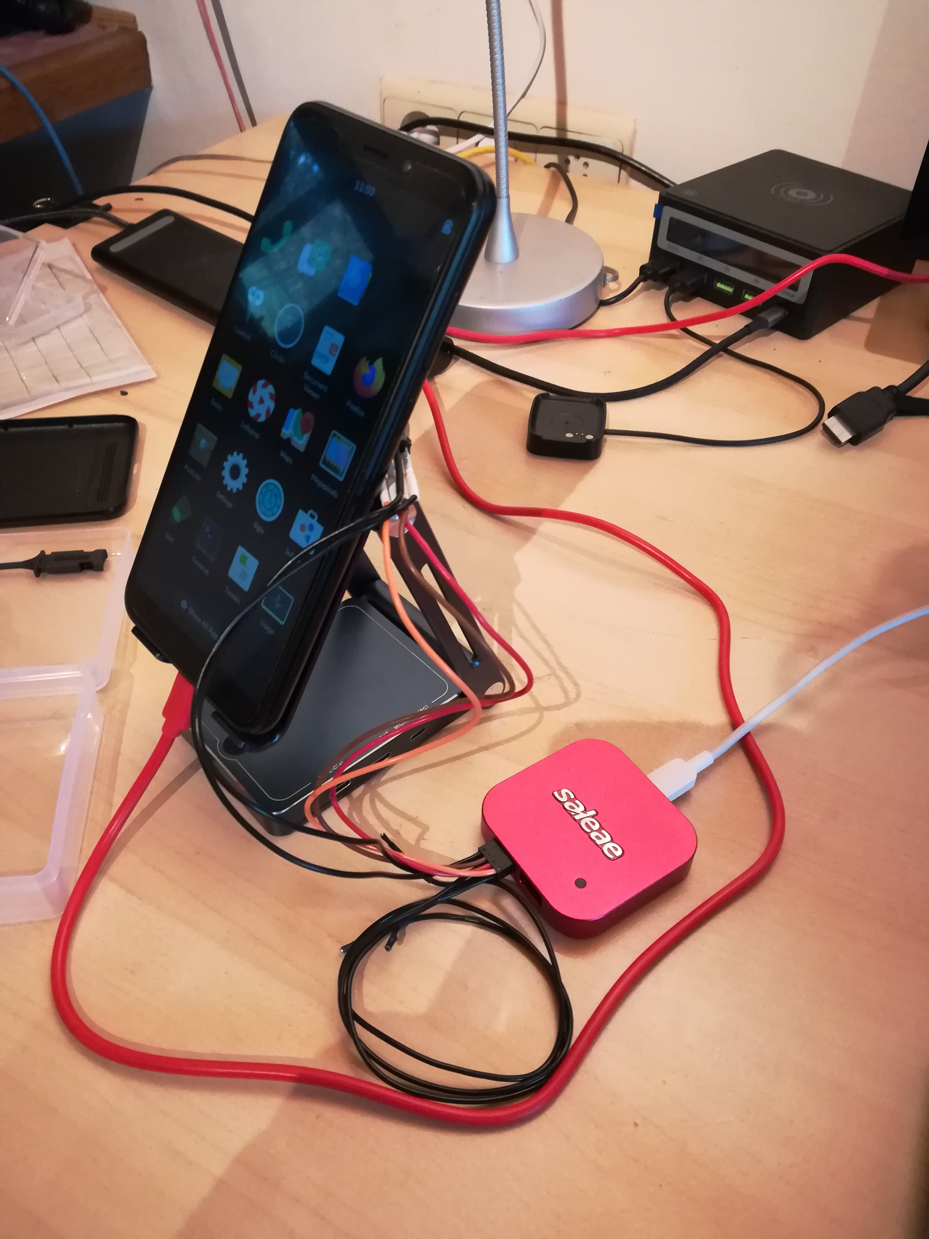
Does it work?
So, the ATtiny is now flashed with the bridge firmware. Let’s install the PCB in the backplate, and the backplate on the Pinephone and let’s see what happens!
The easiest way to check that an I²C device is connected to the bus is by using i2cdetect:
$ sudo i2cdetect -y 2
     0  1  2  3  4  5  6  7  8  9  a  b  c  d  e  f
00:                         -- -- -- -- -- -- -- --
10: -- -- -- -- -- -- -- -- -- -- -- -- -- -- -- --
20: -- -- -- -- -- -- -- -- 28 -- -- -- -- -- -- --
30: -- -- -- -- -- -- -- -- -- -- -- -- -- -- -- --
40: -- -- -- -- -- -- -- -- -- -- -- -- -- -- -- --
50: -- -- -- -- -- -- -- -- -- -- -- -- -- -- -- --
60: -- -- -- -- -- -- -- -- -- -- -- -- -- -- -- --
70: -- -- -- -- -- -- -- --
IT WORKS! As you can see, i2cdetect found a device at address 0x28, which is exactly the address that is mentioned in the firmware source code
!
What’s next ?
So now, the ATtiny84 is running a firmware that is connected to the I²C bus. The next step is to try to communicate with the SX1262 LoRa module from the LoRa backplate via that ATtiny84 that bridges the I²C from the PinePhone to the SPI of the LoRa module!