PineDio is a new product range at Pine64 based on LoRa. Those products include a LoRa gateway, a USB-LoRa adapter, a LoRa backplate for the PinePhone and an embedded development kit based on the RISC-V BL604 MCU. You’ll find more info about PineDio on the wiki .
Those products are not yet available for sale, as we are still working on bringing them up and running by writing software and drivers for them.
A few months ago, Pine64 sent the first prototype version of the PineDio STACK to a few developers (me included). We detected a few issues regarding the JTAG implementation and couldn’t get the LCD to work correctly.
Then, a couple of weeks ago, Pine64 sent us the 2nd prototype version of this development kit. I’ll give a first overview of this new revision in this post.
What is the PineDio STACK?
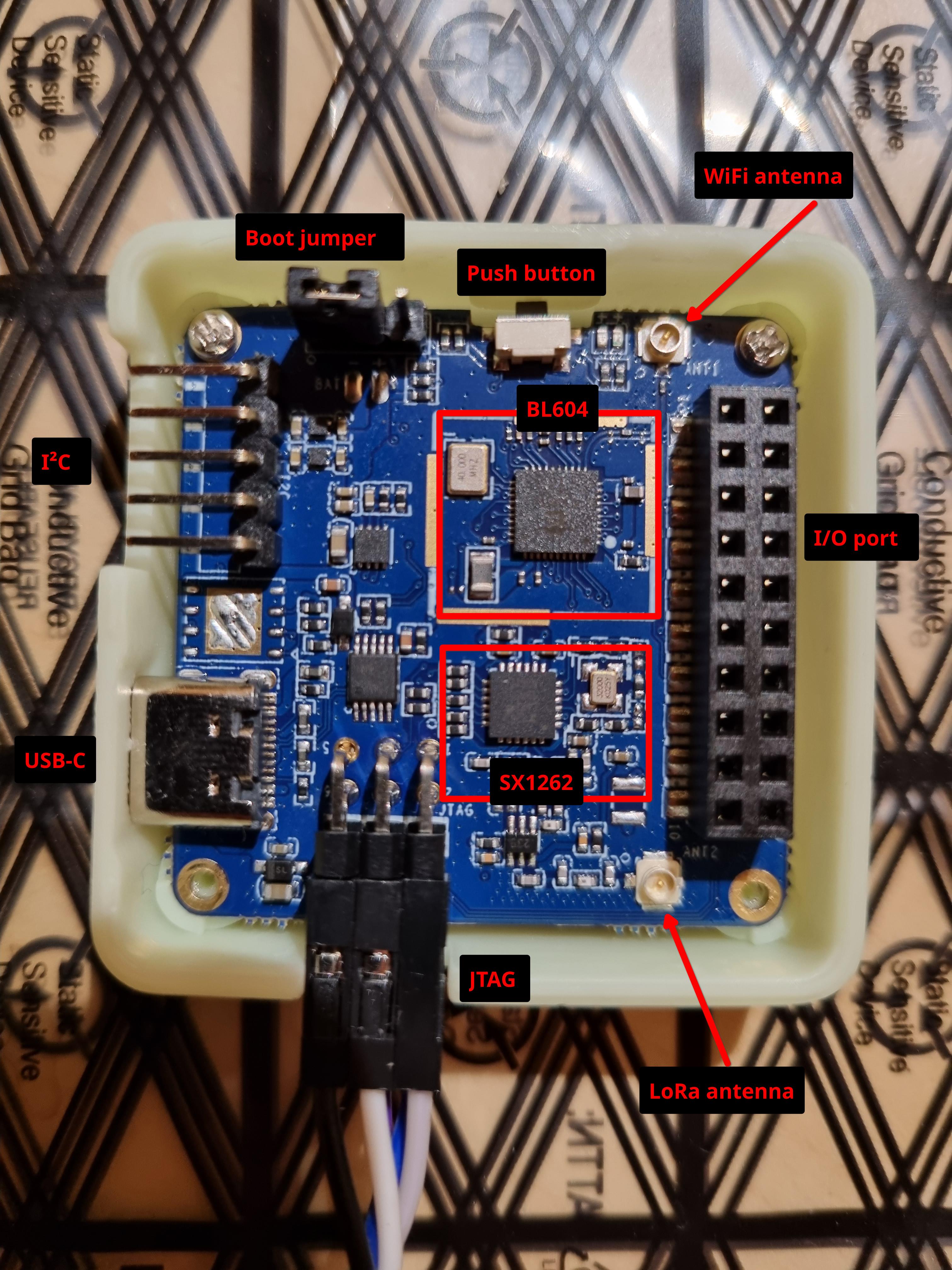
The STACK is an embedded development kit based on the RISC-V MCU BL604 from Bouffalo . It’s a WIFI/BLE MCU running at 192Mhz and equipped with 276KB of RAM and 128KB of internal flash memory. It’s roughly the same as the BL602 with more I/O.
Next to the BL604, you’ll find a Semtech SX1262 LoRa module . This chip, when connected to an antenna, allows LoRa communication.
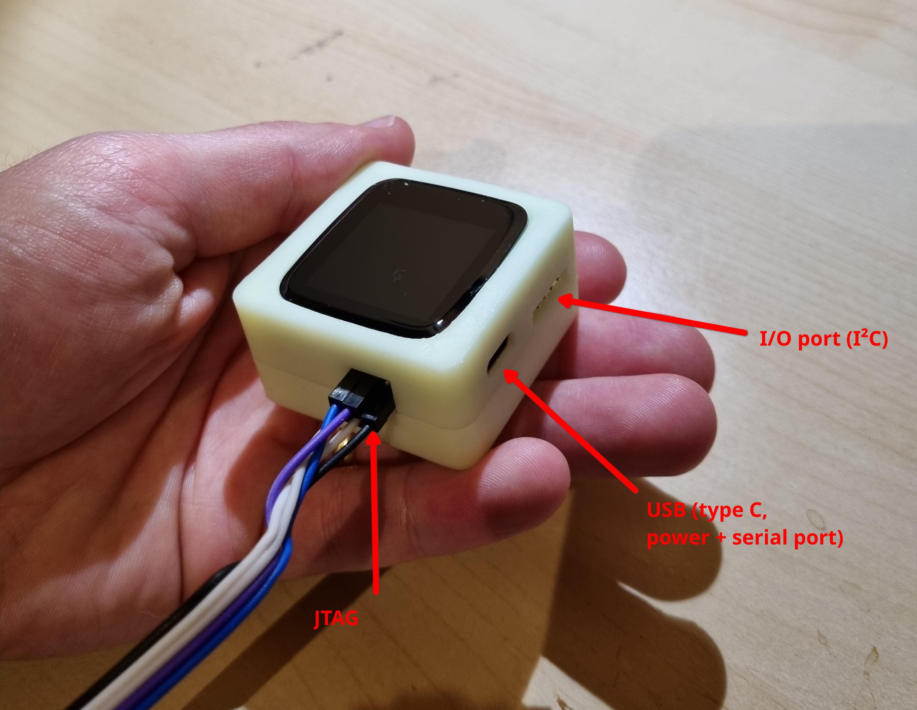
The board is also equipped with a power management unit to power the board and charge an optional battery, a motion sensor, an LCD with touch panel, a (connector for a) heart rate sensor, a vibrator and a few I/O ports.
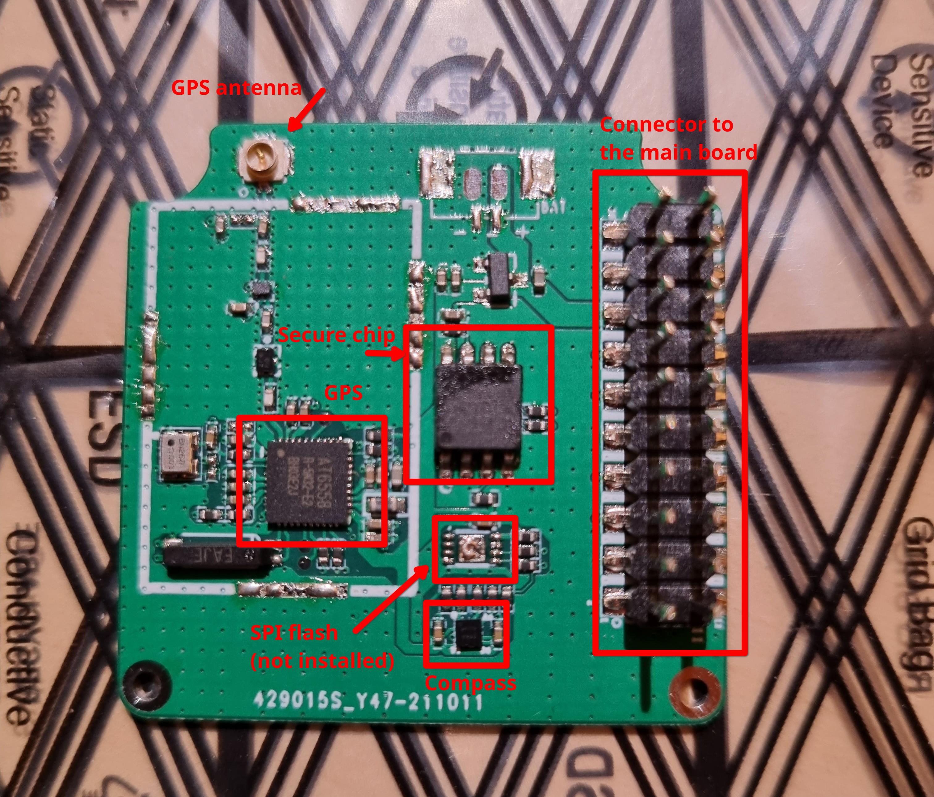
The V2 also came with another board that connects to the main one using the 2x10 pins connector. This board brings a GPS, a compass, a SPI flash and a “secure chip”.
Overall, this is a nice development kit, packed with multiple sensors (motion, compass, heart rate), interfaces (LCD, touch panel), I/O (GPIO, I²C, SPI), radio (WiFi, Bluetooth LowEnergy (BLE), GPS and LoRa) and power options (USB, power pins, battery). I can envision many use-cases for this kit : prototype a new generation of smartwatch (a smartwatch with a LoRa radio looks really fun!), a LoRa end-node, a battery operated LoRa sensor, GPS tracker,…
Schematics and pin mapping
Schematics
- Base board schematics : TODO
- Addon board schematics : TODO
Devices:
- MCU : Bouffalo BL604
- LoRa Module : Semtech SX1262
- LCD : ST7789
- Touch panel : CST816 (to be confirmed)
- Motion sensor : MC3416
- Secure chip : ATECC608A
- GPS : AT655B
- Compass : AK8963C
Pin mapping:
| BL604 Pin | Device pin |
|---|---|
| GPIO0 | SPI MISO |
| GPIO1 | I²C SDA |
| GPIO2 | I²C SCL |
| GPIO3 | GPIO/PMW |
| GPIO4 | GPIO/ADC+PWM |
| GPIO5 | GPIO/ADC+PWM |
| GPIO6 | GPIO/ADC+PWM |
| GPIO7 | UART RX |
| GPIO8 | Boot selector |
| GPIO9 | Touch panel Interrupt |
| GPIO10 | Sx1262 - BUSY |
| GPIO11 | SPI SCK |
| GPIO12 |
What’s next?
First, I would like to check that the issues we found in the first revision of the board are effectively fixed. The main issues where the JTAG port and the display that weren’t working at all.
Then, I would like to port at least parts of InfiniTime to this board to see how well it’s working. I expect the UI to be a lot faster thanks to additional CPU power and faster SPI bus. Also, this MCU has nearly 3x more RAM and twice the flash than the NRF52832. That should give me a lot of room to implement new features based on the LoRa radio and the GPS, for example.