This blog post is part of a series of posts:
- Part 1 : Introduction
- Part 2 : From prototypes to V1.0
- Part 3 : Hardware design
- Part 4 : Software
- Part 5 : Integration with TTN, Node-RED and Home-Assistant
Hardware design
Important notice : I’m a software engineer, and I have very limited knowledge and experience in anything related to hardware design and electronics. I can read a datasheet and a schematics, and I can plug components on a breadboard. But I’ve never designed complete electronic boards and PCB so.. bear with me ;-)
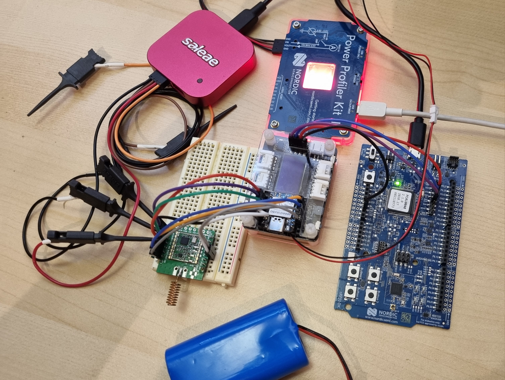
The first prototype was very messy, but it allowed me to implement the whole firmware and check that everything was working as expected.
As you can see on the following picture, I’m using a NRF52DK board as a SWD probe (to flash and debug the firmware). I also use the NRF PPKII as power source and power profiler, and a logic analyzer, the Saleae Logic 8 , to probe various signals from the MCU and LoRa module. There’s also a 4600mAh battery (which was replaced later on by a 1000mAh one).
Once everything was working properly, I cleaned the setup and used a single breadboard. This allowed me to run longer tests.
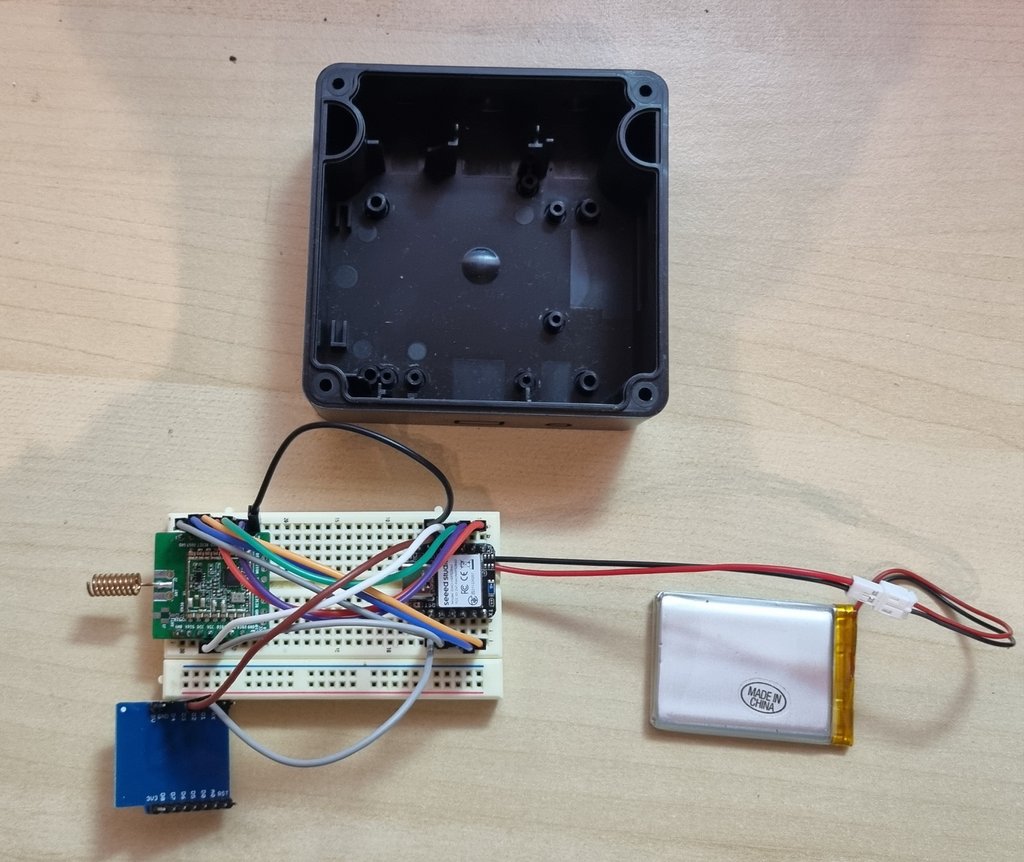
I was very happy with the software but the hardware setup wasn’t “production ready”. This setup on a breadboard is very fragile and unreliable. Plus, I wanted to use this waterproof case I bought when I thought I would use the Lopy board.
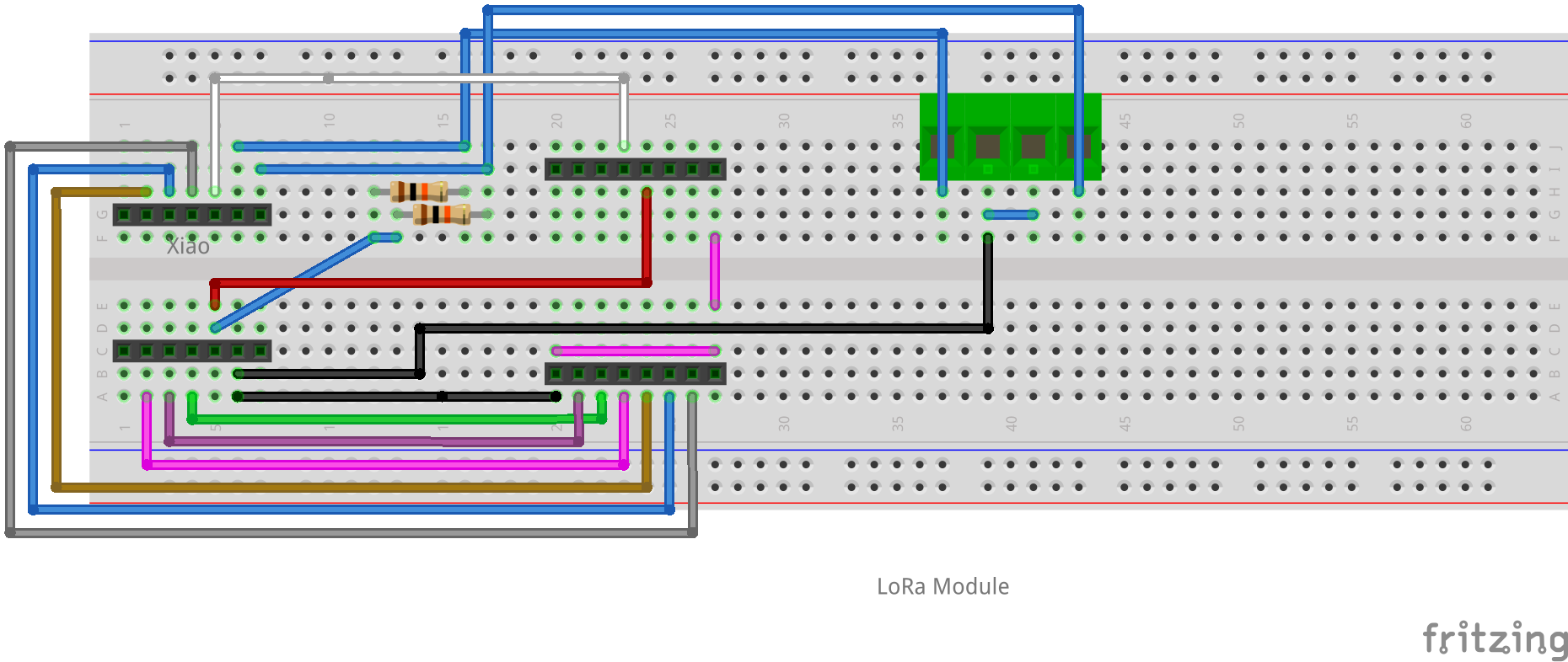
So I decided to try something completely new to me : design a print a PCB! I have never done that, but I remembered that a colleague told me about Fritzing , an open source tool that allows you to draw your circuit on a breadboard and then to design the coresponding PCB. They also run Fritzing Fab a service that builds (prints?) the PCB for you at a affordable price.
So first, I replicated the actual breadboard setup in Fritzing:
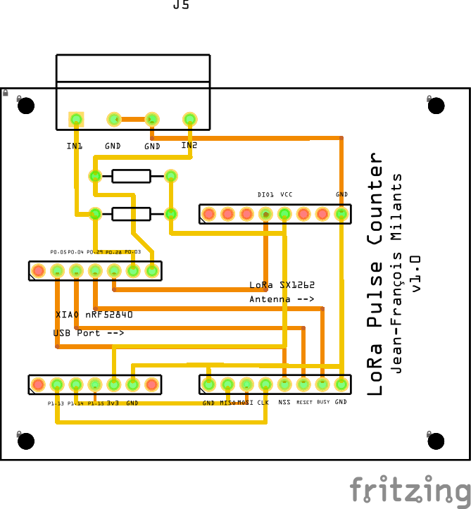
Then I switched to the PCB view and tried to route all the traces on 2 layers (top and bottom). It’s a lot more complicated than I expected : traces cannot cross other traces from the same layer! I spent way more time than expected on this step, but I have to say I’m quite happy with the result.
Before placing the order to print the PCB, I double checked that my measurements were correct by… printing the PCB on a piece of paper, drilling holes for the screws and components and checking that everything fit nicely:
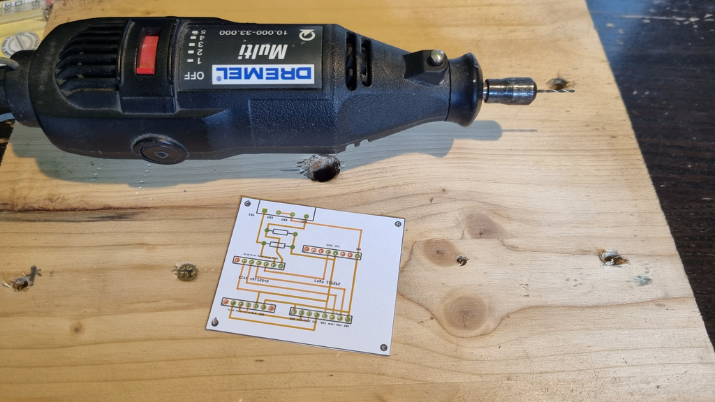
And here is the results after a few adjustements:
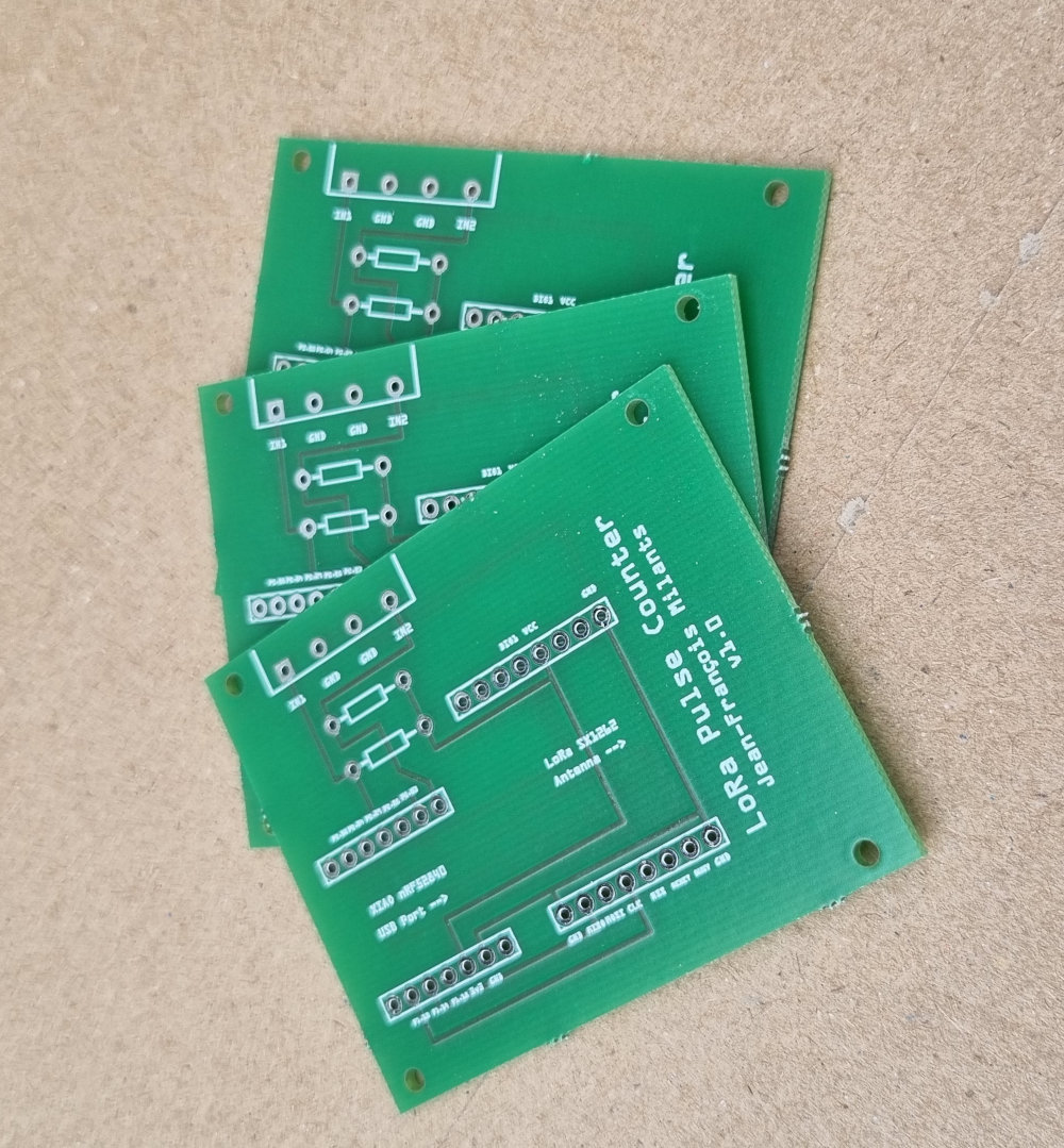
Then, I placed an order to Aisler to build the PCB. The whole process was very easy, even for me! The minium quantity is 3 PCBs, and it cost 24€ (+ shipping) to print them.
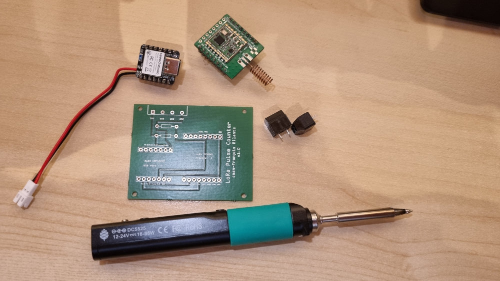
I received the PCBs a few days later:
Next step : solder everything together!
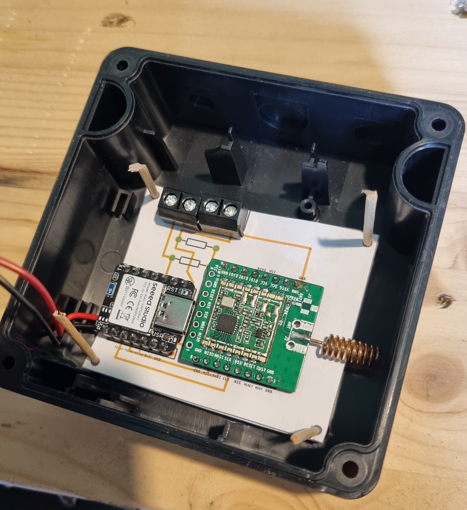
And put everything in the case (the battery is under the PCB):
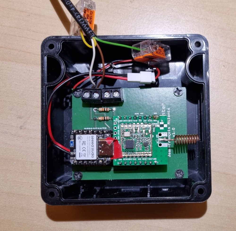
Awesome! Everything fit nicely in the case, and works as expected!
I’ll provide more details on the software implementation in the next part of this series!