This blog post is part of a series of posts:
- Part 1 : Introduction
- Part 2 : From prototypes to V1.0
- Part 3 : Hardware design
- Part 4 : Software
- Part 5 : Integration with TTN, Node-RED and Home-Assistant
Software
The code is fully open source and available on my Codeberg account .
The firmware is written in C, and mostly relies on two 3rd party libraries : LoRaMac-node and LittleFS.
LoRaMac-node is a LoRaWAN stack implementation for end-device, it provides all the code necessary to build a LoRaWAN end device : join the network, send and receive data and many more.
LittleFS provides a fail-safe file system designed for micro controllers and embedded systems. I use this library to store data to non-volatile memory (SPI flash memory). This data is, for example, all the internal context of the LoRaMac-node library.
I tried to keep the code as simple and as straightforward as possible. Remember : my goal was to build this project in a limited amount of time. Which means that I implemented only the functionalities that were absolutely necessary.
The following diagrams shows high level workflow of the firmware:
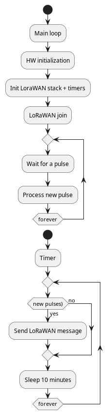
When the device is powered ON, the firmware begins by initializing all the hardware (GPIO pins, SPI bus,…) and the LoRaWAN stack. Then, it enters in an infinite loops that just counts the pulses from the water meter.
During the initialization step, a timer is started. This timer is responsible for sending LoRaWAN message periodically, if new pulses were detected since the last execution of the timer.
The whole application is mostly based on an example provided by LoRaMac-node : periodic-uplink-lpp .
Porting LoRaMac-node
LoRaMac-node
is included in the project as a git submodule in src/LoRaMac-node. The library is highly configurable using compile time variable definitions. Since I use CMake to generate the project, setting those variables is very easy. In this case, I enabled the EU868 region and the SOFT_SE implementation of the secure element.

LoRaMac-node already supports multiple MCUs (STM32, SAML21) and boards NAMote, SAMR34, SKiM,… I don’t know much about those boards, but they are supported out of the box by the project.
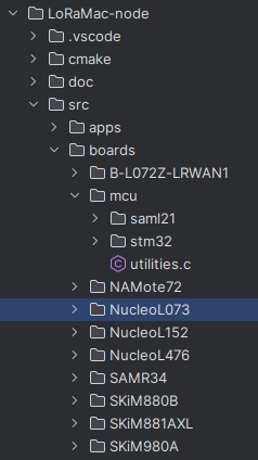
But the project does not support anything related to the NRF52, so I’ll have to implement support for this MCU by myself. Fortunately, the library is well written, and porting the library is mostly a matter of writing low-level code and drivers specific to the MCU and the board it’ll be running on.
In the folder src/boards of LoRaMac-node, we notice that there are many header files (.h) : delay-board.h, gpio-board.h, spi-board.h,… Then, in the folder of each specific board, you’ll find the implementation corresponding to those headers:
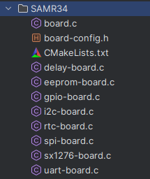
So, basically, all we need to do is to provide an implementation for the functions declared in those headers. For this project, you’ll find the implementation in src/loramac-drivers :
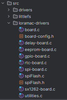
- board.c implements functions related to the board: board initialization, reset, low power management,…
- delay-board.c implements a delay function (sleep for a specified amount of milliseconds).
- eeprom-board contains functions related to the eeprom. Since my board does not have an eeprom, I implemented non-volatile memory using a LittleFS filesystem in the external SPI flash memory.
- gpio-board contains functions related to GPIO management (initialization, read, write, interrupts,…).
- rtc-board implements functions to drive an RTC. The NRF52 does not have a complete RTC peripheral (that manage the date, time, calendar,…) but I managed to emulate the behavior using the RTC timer from the MCU.
- spi-board contains the SPI driver needed to communicate with the SX1262 (the LoRa module) and also the external SPI flash memory.
- sx1262-board.c implement a few functions related to the SX1262 that might change from a board to another.
The most difficult part in the step was probably figuring out what LoRaMac-node expected from the RTC in order to implement the correct behavior. The rest was mostly straightforward.
Once all the functions are implemented, the library should build just fine. Now, we just have to provide a main() function. In this case, I mostly copied/pasted the periodic-uplink-lpp example, as it does exactly what I need (monitor signals and periodically send data over LoRaWAN). The original example monitors the battery voltage. I just needed to add the monitoring of the number of pulses detected. The data is first serialized using Cayenne Low Power Payload
. The message contains a message number, the number of pulses detected since the board was powered on and the battery voltage.
Pulses are detected using the IRQ of the GPIO pin. The handler is implemented in ButtonIrqHandler() and provide a very simple debounce functionality:
int btnCpt = 0;
uint32_t debounceCounter = 0;
void ButtonIrqHandler(void *context) {
  (void) (context);
  uint32_t currentTimerValue = RtcGetTimerValue();

  if (currentTimerValue - debounceCounter > 5) {
    debounceCounter = currentTimerValue;
    btnCpt++;
    NRF_LOG_INFO("Pulse detected. Total : %d", btnCpt);
  }
}
Battery voltage measurement is triggered by a timer:
static void OnBatteryTimerEvent(void *context) {
  (void) (context);
  battery_init(NRF_SAADC_INPUT_AIN7, 14);
  TimerStart(&BatteryTimer);
}
And frame transmission is implemented in PrepareTxFrame():
static void PrepareTxFrame(void) {
  if (LmHandlerIsBusy() == true) {
    return;
  }

  uint8_t channel = 0;

  AppData.Port = LORAWAN_APP_PORT;

  CayenneLppReset();
  CayenneLppAddDigitalInput(channel++, messageCount++);
  CayenneLppAddDigitalInput(channel++, btnCpt);
  CayenneLppAddAnalogInput(channel++, battery_getVoltage() / 1000.0f);

  CayenneLppCopy(AppData.Buffer);
  AppData.BufferSize = CayenneLppGetSize();

  if (LmHandlerSend(&AppData, LmHandlerParams.IsTxConfirmed) == LORAMAC_HANDLER_SUCCESS) {
    // TX confirmed
  }
}
Power optimizations
For this project to run as long as possible on a single battery charge, I needed to ensure that the MCU would go to sleep mode as often as possible and use as little current as possible, especially in sleep mode.
The PineTime community did a great job documenting everything that must be done to reduce the power usage of the PineTime . Since the NRF52832 that powers the PineTime is very similar to the NRF52840 used in this project, all these recommandations also applies to this MCU.
So first, we need to enable the internal DCDC converter and the low frequency clock, in BoardInitMcu() (src/loramac-drivers/board.c
):
// Enable internal DCDC converter, improves power usage
  NRF_POWER->DCDCEN = 1;

  // Init clocks
  nrf_drv_clock_init();
  nrf_drv_clock_lfclk_request(NULL);
  nrfx_clock_lfclk_start();
  while (!nrf_clock_lf_is_running()) {
  }
Then, in BoardLowPowerHandler() (also in src/loramac-drivers/board.c
), we ensure that the SPI flash and SPI peripheral are correctly put to sleep mode and disabled before calling _WFI() to actually put the MCU to sleep. The SPI bus and flash memory obviously need to we woken up when the CPU recovers from sleep mode.
void BoardLowPowerHandler(void) {
  // Put the SPI flash and SPI peripheral to sleep
  SpiFlash_Sleep();
  SpiMaster_sleep(&loraSpiContext);

  // Put the CPU to sleep
  __WFI();

  // CPU has just woken up, wake the SPI peripheral and flash memory up
  SpiMaster_wakeup(&loraSpiContext);
  SpiFlash_Wakeup();
}
Using this implementation, the firmware uses
- 70mA for 1.5s at startup
- 8mA for 1.8s and then 2mA for 750ms during the OTAA join operation
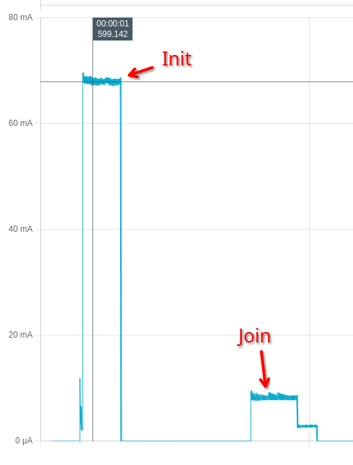
- 17µA in sleep mode
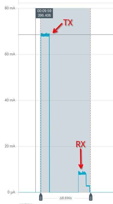
- 68mA for 1s during TX and 8mA for 2s during RX
All in all, it uses an average of 45.33µA when sending a message every 10 minutes.

I’ll probably improve the software in the near future to increase the TX period, and ensure that new messages are sent only if new data is available (if new pulses were detected since the last message, that is).
However, with those current number, the device should theoretically run on a single 1000mAh battery charge for more than 2.5 years, which is already quite nice!
In the next part, I’ll explain how I integrated this sensor with TTN, Node-RED and Home-Assistant!