In previous articles, I introduced the LoRa blackplate for the Pinephone and I flashed the onboard MCU with an SPI<->I²C bridge firmware .
In this post, I’ll write a driver that allows the Pinephone to send ant receive LoRa messages via this LoRa backplate!
How to communicate with the SX1262 ?
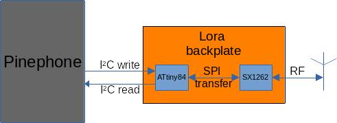
The SX1262 (LoRa radio) is an SPI chip. As the pogo pins only expose and I²C bus, the Pinephone cannot communicate directly with the radio. That’s where the embedded ATtiny84 MCU comes into play : it’ll bridge the I²C bus from the Pinephone with the SPI bus for the SX1262.
This tiny MCU (8-bit AVR running at 8Mhz with 8KB of flash memory and 512 Bytes of RAM) must be flashed with a firmware that does this bridging : receive data from I²C, send them to the SPI device, read the response from the SPI bus and provide it to the I²C bus. I discovered how to flash this firmware in the previous article .
Now, let’s have a look at the source code of this firmware to figure out how it works. Fortunately, the source code is quite simple and small : 162 lines in the main source file .
The main() function is in charge of the initialization :
int main (void)
{
    /* init I2C */
    usiTwiSlaveInit(I2C_ADDR);

    /* set received/requested callbacks */
    usi_onReceiverPtr = I2C_received;
    usi_onRequestPtr = I2C_requested;

    /* enable interrupts */
    sei();

    /* init SPI */
    SPI_init(MOSI, MISO, SCK);
    SPI_begin();
    SPI_setClockDivider(SPI_CLOCK_DIV2);
    SPI_setDataMode(0b00);
    SPI_setBitOrder(MSBFIRST);

    CS_DDR |= (1<<CS);
    CS_PORT |= (1<<CS);

#ifdef DEBUG
    softSerialInit(&DDRB, &PORTB, &PINB, PB1, PB2);
    softSerialBegin(9600);
#endif

	while(true);
}
First, it initializes the I²C (TWI) bus via the function usiTwiSlaveInit(), and provides 2 function pointers that’ll be called back when data is received on the I²C bus or when a read is requested.
Then, it initializes the SPI bus by calling these SPI_xxx() functions.
If the DEBUG constant is defined, it also initializes a serial bus (software implementation) but I cannot use them as those pins are not exposed and/or easily accessible on the PCB.
Finally, it enters into an infinite loop.
… Wait… What? This code does nothing except initializing those busses?
Not exactly! The usi library that is used to drive the I²C bus probably configures interrupts on the bus. This way, the IRQ handler will be called automatically when data are available on the bus, or when the Pinephone will read data.
The functions called by the IRQ handlers are I2C_received() and I2C_requested(). Let’s have a look at them.
I2C_received() is called when data written by the Pinephone is received by the ATtiny :
void I2C_received(uint8_t bytes_recieved)
{
    uint8_t command = usiTwiReceiveByte();

    switch(command) {
        case CMD_TRANSMIT: {
            CS_PORT &= ~(1<<CS);
            for(int i = 1; i < bytes_recieved; i++) {
                uint8_t received_byte = SPI_transfer(usiTwiReceiveByte());
                SPI_buffer[received_index++] = received_byte;
                if(received_index >= BUFFER_SIZE)
                    received_index = 0;
            }
            CS_PORT |= (1<<CS);
            break;
        }
        case CMD_CONFIGURE:
        /* ...*/
    }
}
This function begins by reading the first byte to determine a command. The code implements 2 commands : CMD_TRANSMIT and CMD_CONFIGURE. The most interesting one is of course CMD_TRANSMIT.
The case for this command simply reads all consecutive bytes from the I²C bus and write them on the SPI bus. Note that the SPI bus always read and write 1 byte at the same time, there’s no separate read and write procedure like on the I²C bus, for example.
That’s why each time a byte is written to the SPI device, 1 byte is also read at the same time. This read byte is stored in SPI_buffer, which is an array of 128 bytes managed as a circular buffer:
#define BUFFER_SIZE 128
uint8_t SPI_buffer[BUFFER_SIZE];
I2C_requested() is called whenever the host (the Pinephone) requests data on the bus. This function is really simple, at it simply take a byte out of SPI_buffer and send it t the I²C host.
void I2C_requested() {
    usiTwiTransmitByte(SPI_buffer[transmit_index++]);
    if(transmit_index >= BUFFER_SIZE)
        transmit_index = 0;
}
According to this code, we can now decude the I²C protocol the Pinephone will have to implement:
- To write data from the Pinephone to the SX1262, you send a buffer with the byte
CMD_TRANSMIT(0x01) followed by the bytes you want to write to the device. Which means that you’ll always write 1 byte more than the original buffer. - To read data from the SX1262 to the Pinephone, simply read data on the I²C bus. You’ll automatically receive all the data that were read from the SX1262 during the last write command.
- Note that you’ll have to carefully read all data that were read from the SPI device to ensure that the receive and transmit indexes in the circular buffer are in sync.
A C driver
Now, we have all the information necessary to write a C driver that will run on the Pinephone to communicate with the SX1262 via the ATtiny!
First, we open the I²C port. Remember, in Linux, everything is a file:
char *filename = "/dev/i2c-2";
if ((i2cFile = open(filename, O_RDWR)) < 0) {
 /* ERROR */
}
Then, we configure the address of the device we want to talk to:
int addr = 0x28; // The I2C address of the ATtiny running the bridge firmware
if (ioctl(i2cFile, I2C_SLAVE, addr) < 0) {
  /* ERROR */
}
Finally, we can write data:
uint8_t buffer[size+1];
buffer[0] = 1; // CMD_TRANSMIT
memcpy(buffer+1, dataToWriteToTheSx1262, size);
if (write(i2cFile, buffer,size+1) != size+1) {
  /* ERROR */
}
And we can also read data:
uint8_t buffer[size];
for(int i = 0; i < size; i++) {
    if (read(i2cFile, buffer, 1) != 1) {
      /* ERROR */
    }
  }
NOTE : for some reason, I couldn’t read all the bytes at once, only the first one would contain valid data. That’s why I implemented the read operation in a loop where each iteration reads one byte.
Let’s talk LoRa!
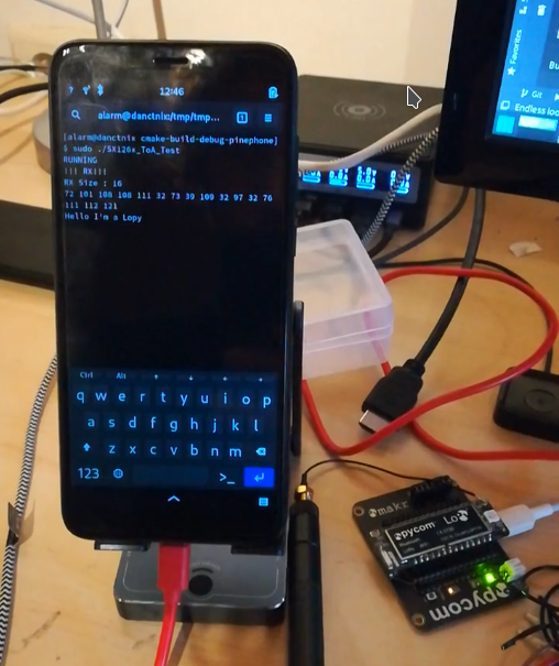
Now that we have basic routines to initialize the bus, and read and write data to and from the bus, we can easily write a small test program that sends commands to the SX1262 to send and receive LoRa messages. I’ll publish the code as soon as I have the opportunity to clean it and wrap it into a nice CMake project!
The following picture shows my test program that receives LoRa packets from a PyCom Lopy board (on the bottom right of the picture):
What’s next ?
I’ll polish the different projects I created for the PineDio STACK, the PineDio USB adapter and this PineDio LoRa backplate for the Pinephone so that I can publish them.
Then, I would like to make a demo of these 3 devices communicating together!