Bouffalo has recently released their new chips : the BL616 and BL618 RISC-V MCU. Equipped with a WiFi6 + Bluetooth5 + Zigbee radio, this 32bit RISC-V single core chip runs at up to 320Mhz and is supported by 532KB of SRAM memory. Different variants of the chips exist with integrated flash and pSRAM memory. It also supports external flash and pSRAM memory.
I was lucky enough to receive one of the first BL61X_MB development board. My board hosts a BL618M05, the “multimedia” variant that is equipped with WiFi6+BT+BLE+Zigbee radios and 32Mb of internal pSRAM. The board also provides a 16MB SPI flash memory.
In this article, I’ll introduce the board and explain how to get started with it : flash a new firmware image with the serial bootloader, run the firmware and debug it with the embedded CKLink probe and with OpenOCD.
Table of content
Presentation of the board
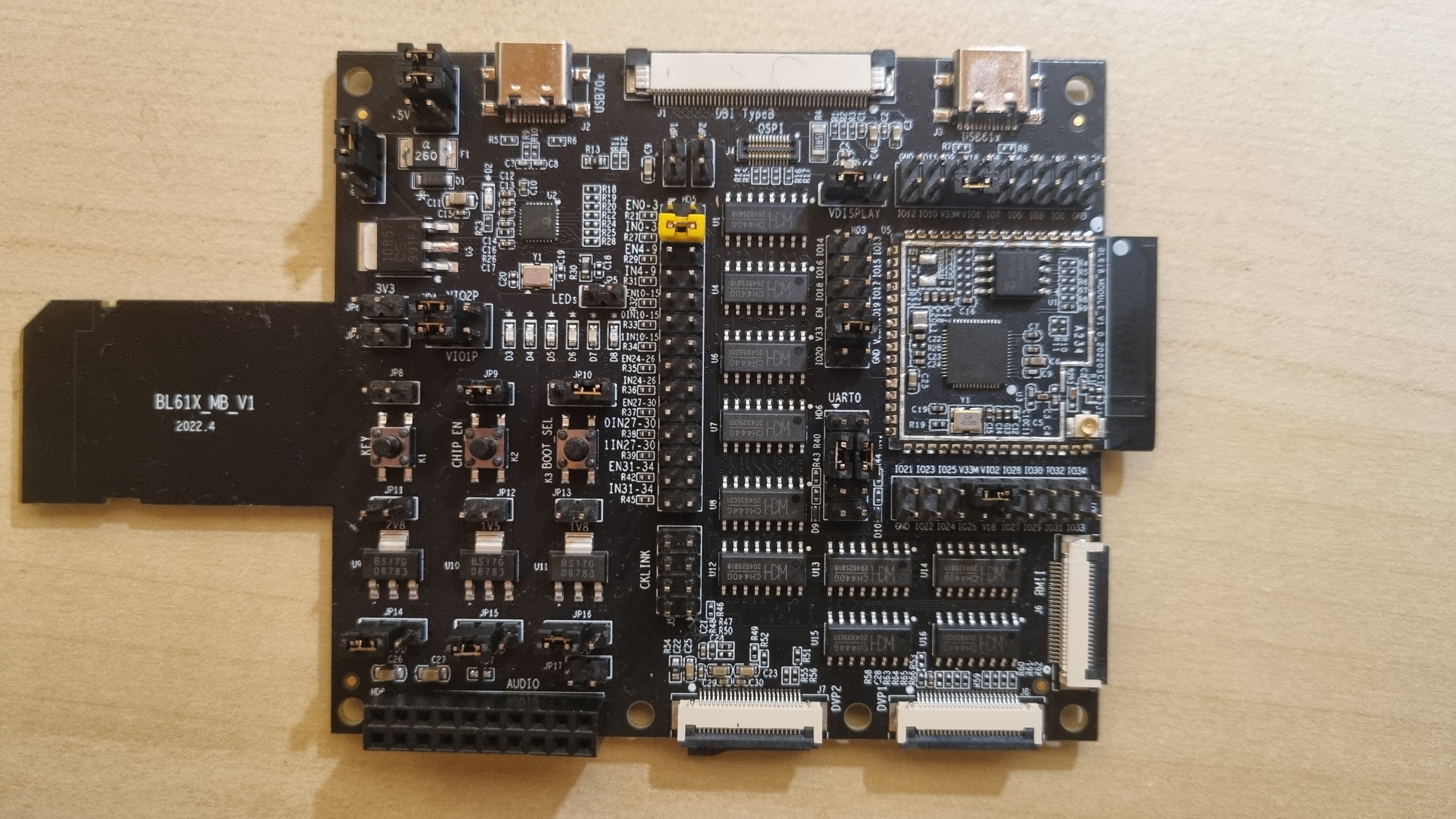
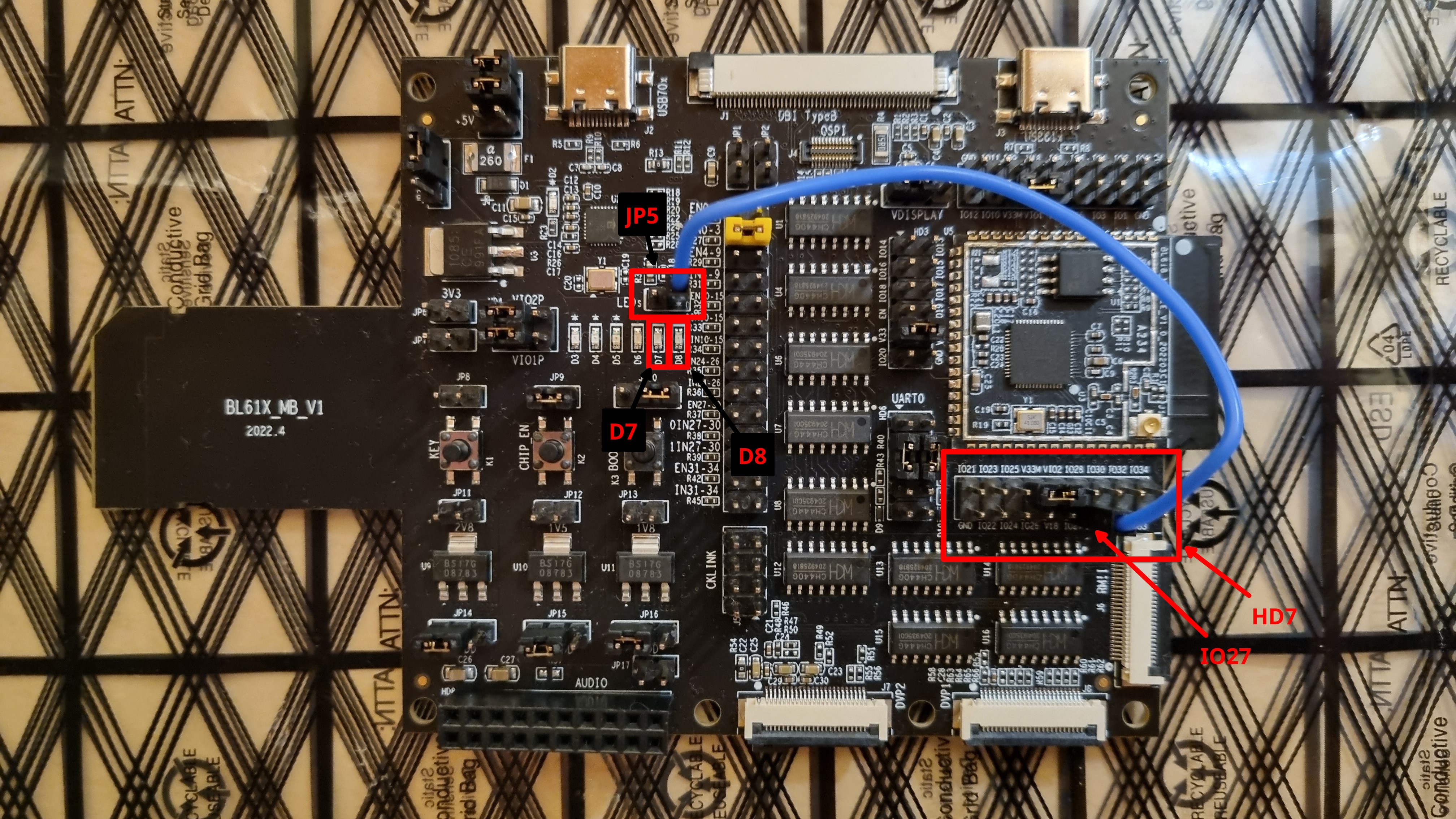
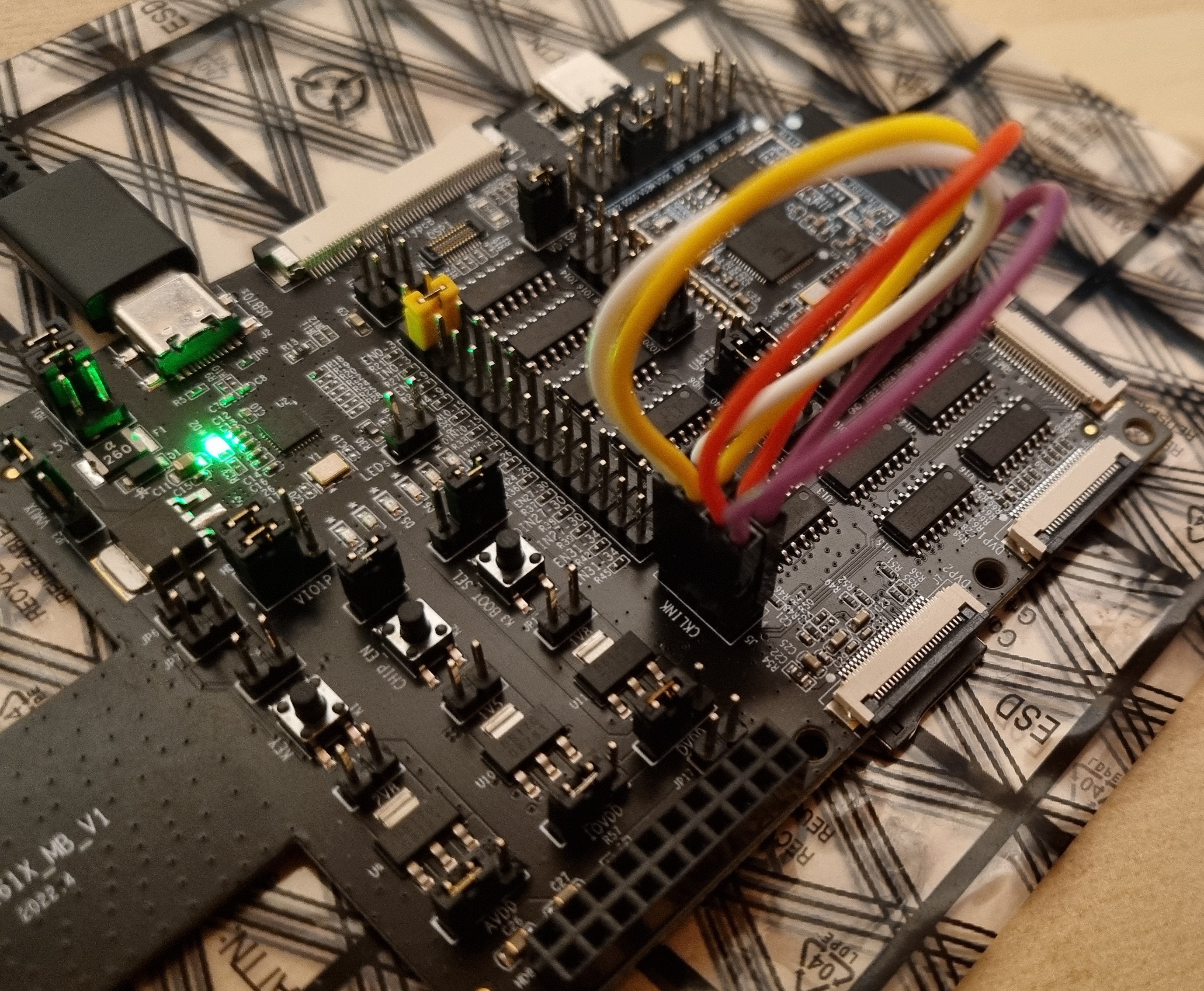
Here the layout of the board with most important parts hightlighed:
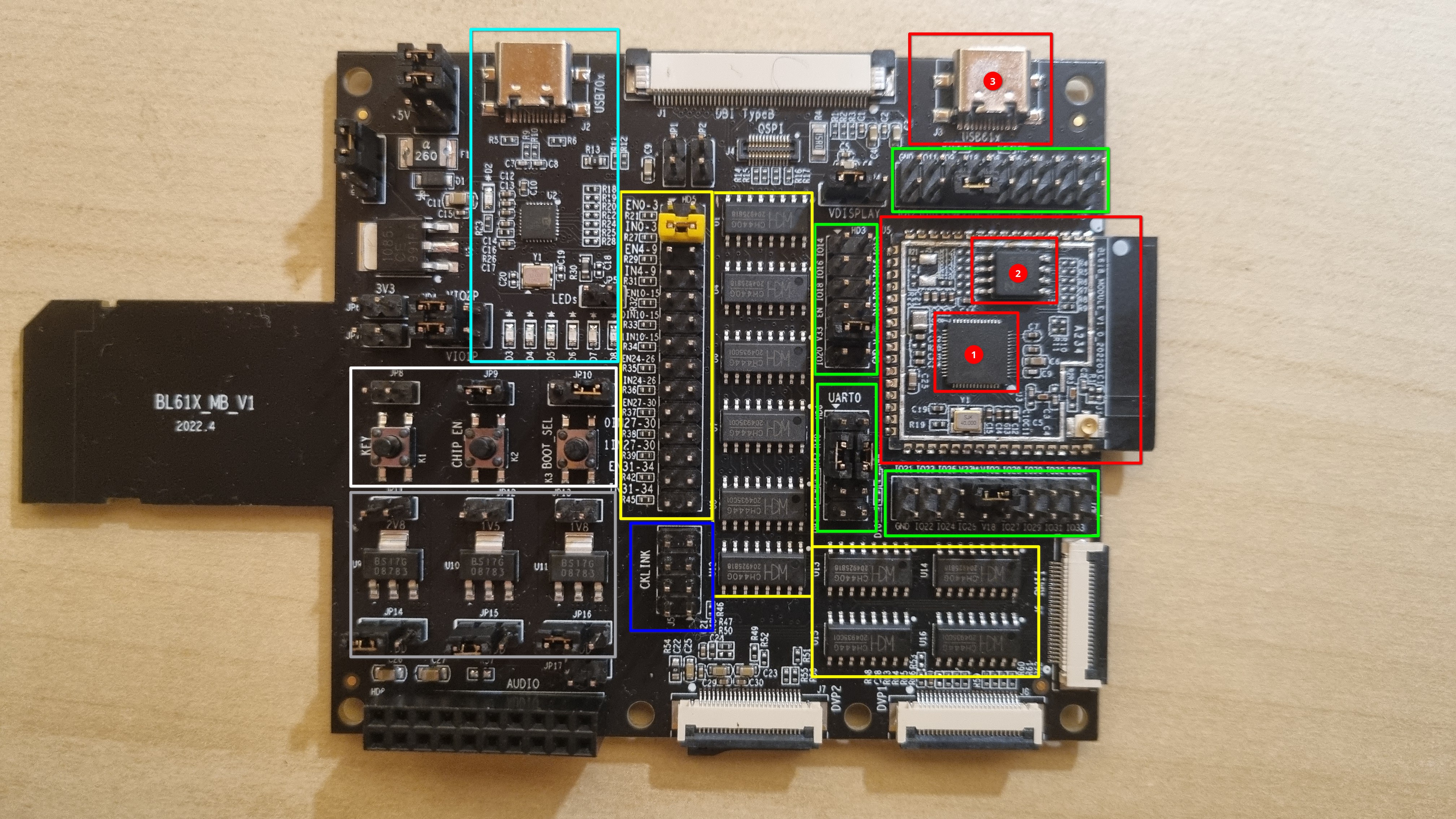
- In red : the BL618 module with the BL618 chip (1), the external SPI flash chip (2) and the USB port (3).
- In green : the pin headers connected to the GPIOs of the BL618
- In blue : the JTAG debug port
- In yellow : switches that routes signals from the BL618 to mu connectors
- In cyan : the integrated BL702 (and its USB port) that acts as an embedded CKLink (JTAG) debug probe and USB/serial adapter
- In white : 3 buttons and corresponding jumpers. The jumpers allows for example to connect pins from the BL702 so that the flashing application (BLDevCube) can automatically switch bootmode and reset the BL618 while flashing.
- Key
- CHI_EN (reset)
- BOOT_SEL (boot mode : bootloader or application)
- In grey : the voltage converters for the board (chip + external display)
Examples : Hello world and blinky
Setup the SDK & toolchain
Let’s build two simple code examples to test the board : helloworld and blinky (gpio test).
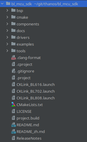
For this, you’ll want to download the bl_mcu_sdk
, the SDK provided by Bouffalo to support their chips.
$ git clone https://github.com/bouffalolab/bl_mcu_sdk.git
$ cd bl_mcu_sdk
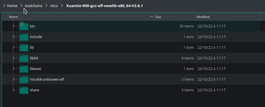
You’ll also need to download the T-Head toolchain to build the application. The links to the toolchain is provided in the README.md of the SDK file. Simply download the archive and uncompress it wherever you want.
Helloworld
The SDK provides many examples in the directory examples/.
Let’s start with the helloworld example which is a simple application that writes helloworld on the serial console. The code is pretty straightforward:
#include "bflb_mtimer.h"
#include "board.h"
#include "log.h"

int main(void)
{
    board_init();
    while (1) {
        LOG_F("hello world\r\n");
        LOG_E("hello world\r\n");
        LOG_W("hello world\r\n");
        LOG_I("hello world\r\n");
        LOG_D("hello world\r\n");
        LOG_T("hello world\r\n");
        bflb_mtimer_delay_ms(1000);
    }
}
It initializes the MCU and the board and then enters into an infinite loop that logs “hello world” in multiple log levels every 1 second.
To build this example:
$ cd examples/helloworld
$ make CHIP=bl616 BOARD=bl616dk
The SDK presumes that the toolchain (riscv64-unknown-elf-gcc) is available in your $PATH. You can also provide the full path to the toolchain by defining the variable CROSS_COMPILE:
$ cd examples/helloworld
$ make CHIP=bl616 BOARD=bl616dk CROSS_COMPILE=/path/to/the/toolchain/Xuantie-900-gcc-elf-newlib-x86_64-V2.6.1/bin/riscv64-unknown-elf-
The firmware is built in examples/peripherals/gpio/gpio_input_output/build/build_out/helloworld_bl616.bin
Blinky
Bouffalo also provides a GPIO example in examples/peripherals/gpio/gpio_input_output. For the sake of this article, I’ve slighted modified this example:
#include "bflb_gpio.h"
#include "board.h"

struct bflb_device_s *gpio;

int main(void)
{
    board_init();

    gpio = bflb_device_get_by_name("gpio");
    bflb_gpio_init(gpio, GPIO_PIN_27, GPIO_OUTPUT | GPIO_PULLUP | GPIO_SMT_EN | GPIO_DRV_0);

    while (1) {
        printf("GPIO set to 1\r\n");
        bflb_gpio_set(gpio, GPIO_PIN_27);
        bflb_mtimer_delay_ms(200);

        printf("GPIO set to 0\r\n");
        bflb_gpio_reset(gpio, GPIO_PIN_27);
        bflb_mtimer_delay_ms(200);
    }
}
The original example initializes 2 GPIOs (1 input, 1 output) and would set/reset the output and read the input in a loop.
In this modified version, a single output is initialized on GPIO27. Then, the loop will simply set this output to 1 and 0 every 200ms. It also prints a message on the serial console.
By default, there’s no LED connected to the MCU. But, according to the schematics of the board, LEDs D7 and D8 are not connected to anything except the header JP5. You can then use a jumper wire to connect GPIO27 from HD7 to any of the pins of JP5. When you run this application, the corresponding LED should blink.
To build this example:
$ cd examples/peripherals/gpio/gpio_input_output
$ make CHIP=bl616 BOARD=bl616dk CROSS_COMPILE=/path/to/the/toolchain/Xuantie-900-gcc-elf-newlib-x86_64-V2.6.1/bin/riscv64-unknown-elf-
The firmware is built in examples/peripherals/gpio/gpio_input_output/build/build_out/gpio_input_output_bl616.bin
Flash a new firmware using the serial bootloader
Hardware setup
When you connect the left USB-C port (labelled USB70X), your computer should detect a new serial port (/dev/ttyACM0 in my case). This serial port can be used by your application as a console output, for example, and is also used by the serial bootloader.
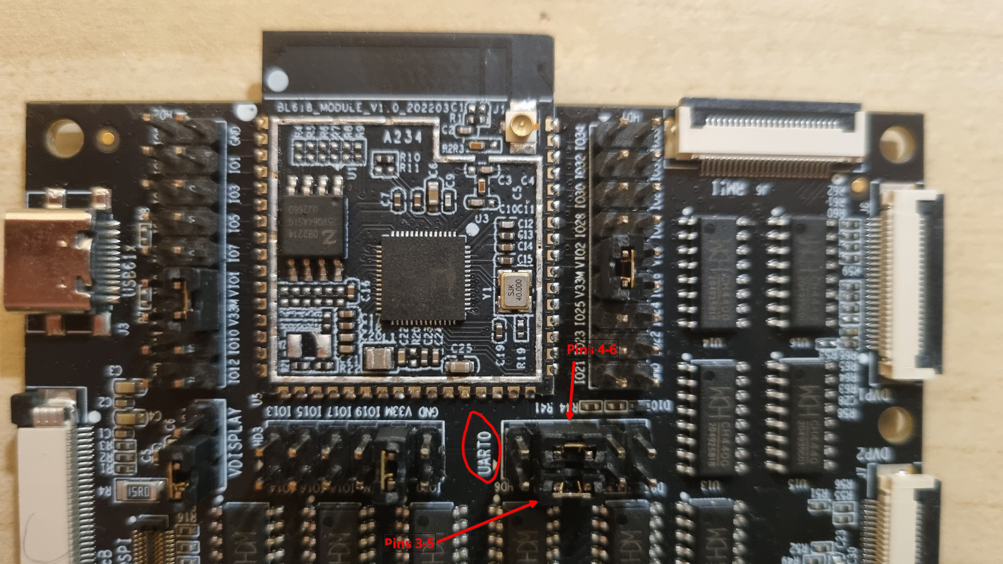
First, check that the serial port from the BL702 is connected to the UART pins of the BL618 using jumpers on HD6:
- pins 3 and 5 must be connected together
- pins 4 and 6 must be connected together
To flash a new firmware, you first need to boot the BL618 in bootloader mode :
- push and keep pushed the BOOT_SEL button
- press and release the BOOT_EN button
- release the BOOT_SEL button
Flashing applications can use the CTS and RTS pins from the serial port to automatically switch the bootmode and reset the chip. To enable this, you need to connect 2 jumpers:
- 1 jumper on JP9 (pins 1-2)
- 1 jumper on JP10 (pins 2-3, the two pins on the right)
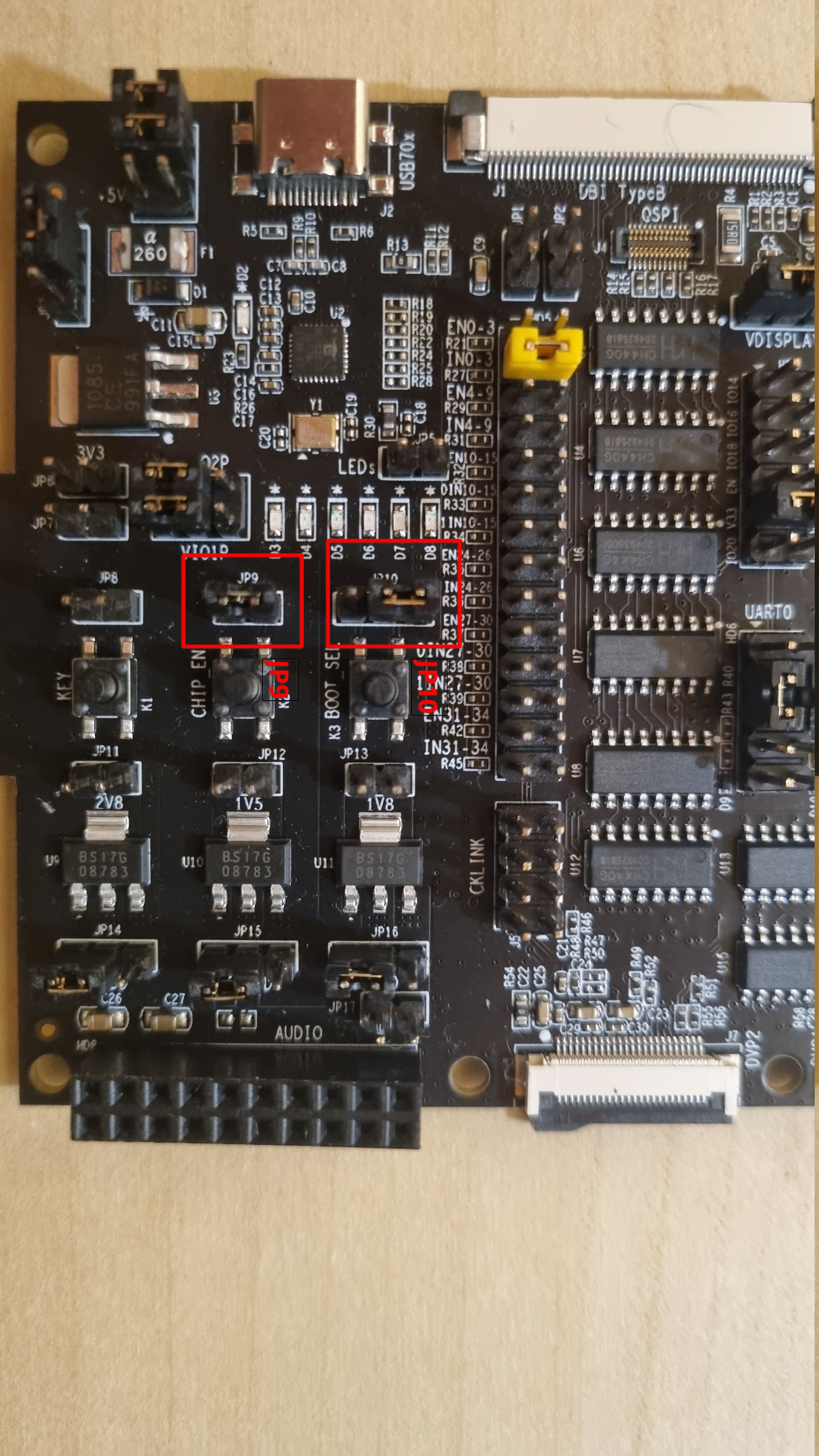
These jumpers connect pins from the ISP (the integrated BL702) to the BL618 pins (reset and bootmode).
Then, you can use your favorite flashing application to flash the firmware. Simply press the BOOT_EN button again to reset in application mode.
Note that to my knowledge, only BlDevCube supports the BL61x chips but othere applications like Blisp will hopefully support these chips soon!
Flash the firmware using BlDevCube
First, download and uncompress Bouffalo Lab Dev Cube from their website
. Unzip it and simply run BLDevCube-ubuntu (if you’re on Linux, of course). The MCU selection window opens:
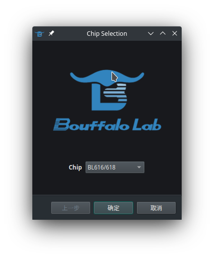
Select the option BL616/618 and press ENTER. The main window opens:
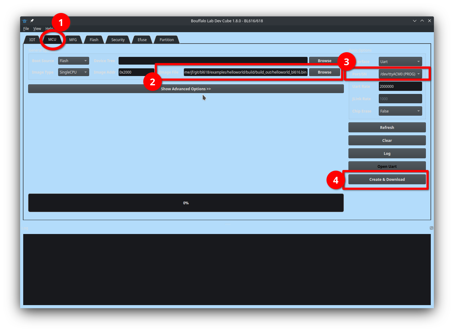
- Open the tab MCU
- Specify the path to the firmware (
.binfile) - Select the serial adapter (connect your PC on the leftmost USB port labelled USB70x and hit Refresh is it’s not listed)
- Reset the board in bootloader mode if you didn’t connect the ISP jumpers on JP9 and JP10 (see above)
- Hit the button Create & download
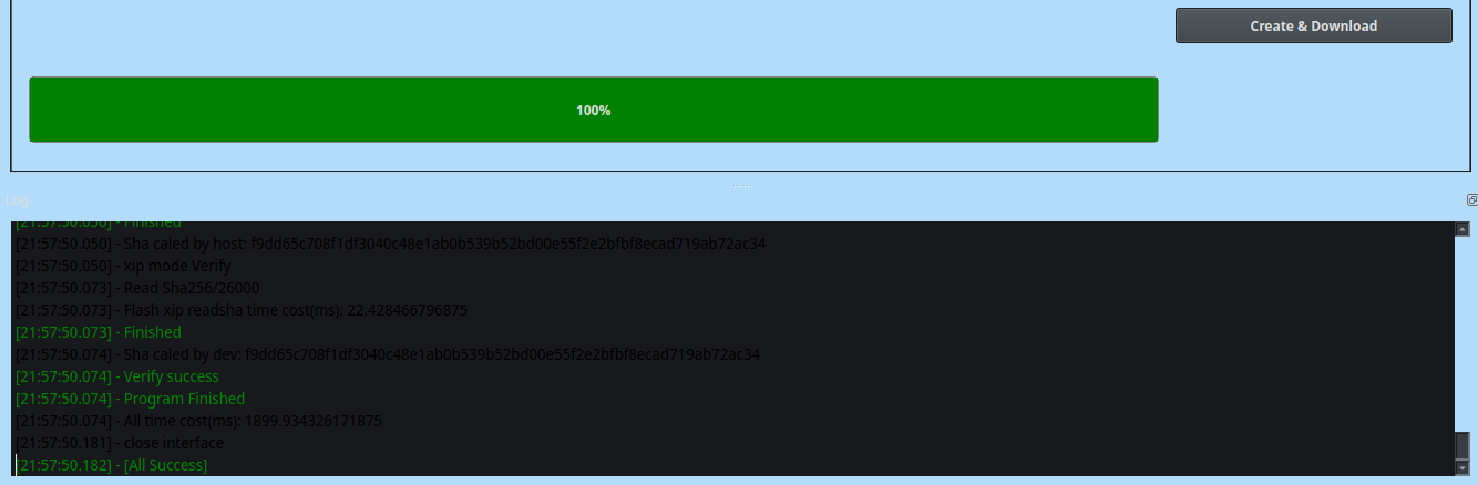
Wait a few seconds and… done!
To run the firmware, simply reset the MCU by pressing the button BOOT_EN without pressing BOOT_SEL.
To monitor the serial output, use you favorite terminal application (picocom in this example) :
$ picocom --baud 2000000 /dev/ttyACM0


  ____               __  __      _       _       _
 |  _ \             / _|/ _|    | |     | |     | |
 | |_) | ___  _   _| |_| |_ __ _| | ___ | | __ _| |__
 |  _ < / _ \| | | |  _|  _/ _` | |/ _ \| |/ _` | '_ \
 | |_) | (_) | |_| | | | || (_| | | (_) | | (_| | |_) |
 |____/ \___/ \__,_|_| |_| \__,_|_|\___/|_|\__,_|_.__/

Build:21:55:59,Jan 10 2023
Copyright (c) 2022 Bouffalolab team
=========== flash cfg ==============
jedec id   0x5E4017
mid            0x5E
iomode         0x04
clk delay      0x01
clk invert     0x01
read reg cmd0  0x05
read reg cmd1  0x35
write reg cmd0 0x01
write reg cmd1 0x31
qe write len   0x01
cread support  0x01
cread code     0x20
burst wrap cmd 0x77
=====================================
dynamic memory init success,heap size = 349 Kbyte
sig1:ffffffff
sig2:0000f32f
cgen1:9f7ffffd
hello world
hello world
hello world
hello world
Debug the firmware
The BL61x MCU provides a JTAG debugging interface which allows more advanced debugging than the good ol’ “printf” debugging technique.
Bouffalo provides 2 ways for debugging : CKLink and OpenOCD (they added the OpenOCD configuration files very recently ).
CKLink
T-Head DebugServer
The onboard BL70x is running with a firmware that implements CKLink, so it mostly works out of the box! You just to download T-Head-DebugServer (that is unfortunately only available as binaries for Linux x86_64 and Windows). Bouffalo provides download links here . Or, if you understand chinese, you can also try to create an account and download if from T-Head website .
Note that this is a .sh script that, when run, unzips the content of an embedded archive into /usr/lib, /usr/bin,…
I do not like this very much, so I extracted the archive out of the shell script and then uncompressed it in my home directory. This way, I did not need to alter my system. Here’s how to do this.
First, open the .sh file and find the line that begins with LNUM= :
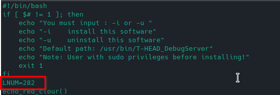
This number is the line number where the content of the archive is written into the file. You can then simply use tail to extract the archive into another file:
tail -n +282 ./T-Head-DebugServer-linux-x86_64-V5.16.5-20221021.sh > theaddebugserver.tar.gz
And then uncompress the archive theaddebugserver.tar.gz wherever you want.
Hardware setup
Before starting any debugging session, you’ll first have to connect 4 pins from the BL702 to the JTAG pins of the BL618 : simply install a jumper (or jumper wires) on all 4 pins of J5 (CKLINK) :
CLI debugging
Connect your board (USB70x port) to your computer and run T-Head DebugServer :
./DebugServerConsole.elf ✔
+--- ---+
| T-Head Debugger Server (Build: Oct 21 2022) |
User Layer Version : 5.16.05
Target Layer version : 2.0
| Copyright (C) 2022 T-HEAD Semiconductor Co.,Ltd. |
+--- ---+
T-HEAD: CKLink_Lite_V2, App_ver unknown, Bit_ver null, Clock 2526.316KHz,
5-wire, With DDC, Cache Flush On, SN CKLink_Lite_Vendor-rog D11B79.
+-- Debug Arch is RVDM. --+
+-- CPU 0 --+
RISCV CPU Info:
WORD[0]: 0x0814050d
WORD[1]: 0x11080000
WORD[2]: 0x202bf97b
MISA : 0x40909125
Target Chip Info:
CPU Type is E907FP, Endian=Little, Version is R1S2P0.
DCache size is 16K.
ICache size is 32K.
MGU zone num is 8.
MGU zone size is 4B.
HWBKPT number is 3, HWWP number is 3.
MISA: (RV32IMAFCXP, Imp M-mode, U-mode)
GDB connection command for CPUs(CPU0):
target remote 127.0.0.1:1025
target remote 192.168.1.221:1025
**************** DebuggerServer Commands List **************
help/h
Show help informations.
*************************************************************
DebuggerServer$
Then start GDB and connect to your board:
$ /home/jf/toolchains/riscv/Xuantie-900-gcc-elf-newlib-x86_64-V2.6.1/bin/riscv64-unknown-elf-gdb
GNU gdb (Xuantie-900 elf newlib gcc Toolchain V2.6.1 B-20220906) 10.0.50.20200724-git

[...]

(gdb) target remote 127.0.0.1:1025
Remote debugging using 127.0.0.1:1025
warning: No executable has been specified and target does not support
determining executable automatically.  Try using the "file" command.
0x90016ff6 in ?? ()
Enter a few initialization commands (inspired from their .launch configuration files for Eclipse):
set trace-commands on

define bl-reset
set $pc=0xA0000000
set $mie=0
set $mstatus=0x1880
thb main
end

define target hookpost-remote
bl-reset
end

set mem inaccessible-by-default off
set architecture riscv:rv32
set remotetimeout 250

mem 0x42FC0000 0x43010000 rw
mem 0x62FC0000 0x63010000 rw
#rom
mem 0x90000000 0x90020000 ro
#psram
#flash
mem 0xA0000000 0xA0400000 ro
Load the .elf file corresponding to the running firmware so GDB can figure out the symbols and check out the current back trace with the command bt.
(gdb) file /home/jf/git/bl618/examples/helloworld/build/build_out/helloworld_bl616.elf
A program is being debugged already.
Are you sure you want to change the file? (y or n) y
Reading symbols from /home/jf/git/bl618/examples/helloworld/build/build_out/helloworld_bl616.elf...
(gdb) bt
#0  0x62fc00ac in bflb_mtimer_get_time_us () at /home/jf/git/bl618/drivers/lhal/src/bflb_mtimer.c:56
#1  0x62fc0138 in bflb_mtimer_get_time_ms () at /home/jf/git/bl618/drivers/lhal/src/bflb_mtimer.c:69
#2  bflb_mtimer_delay_ms (time=time@entry=1000) at /home/jf/git/bl618/drivers/lhal/src/bflb_mtimer.c:84
#3  0xa0003e2c in main () at /home/jf/git/bl618/examples/helloworld/main.c:15
Type continue to continue the execution, and CTRL+C to stop it.
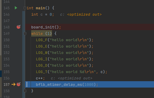
Since the code is currently running from flash memory (no writable by GDB), you cannot use standard breakpoints. Instead, you have to use hardware breakpoints with the command hbreak:
(gdb) hbreak main.c:11
Hardware assisted breakpoint 1 at 0xa0003e14: file /home/jf/git/bl618/examples/helloworld/main.c, line 11.
(gdb) continue
Continuing.

Breakpoint 1, main () at /home/jf/git/bl618/examples/helloworld/main.c:11
11              LOG_W("hello world\r\n");
And that’s it! I currently couldn’t find any reliable way to reset the MCU, unfortunately. I couldn’t find anyway to flash the firmware in the MCU via JTAG and GDB either.
Debugging with CLion
CLI debugging is cool, but I also enjoy the comfort of my favorite IDE : CLion. Note that Bouffalo provides configuration files for Eclipse in their SDK.
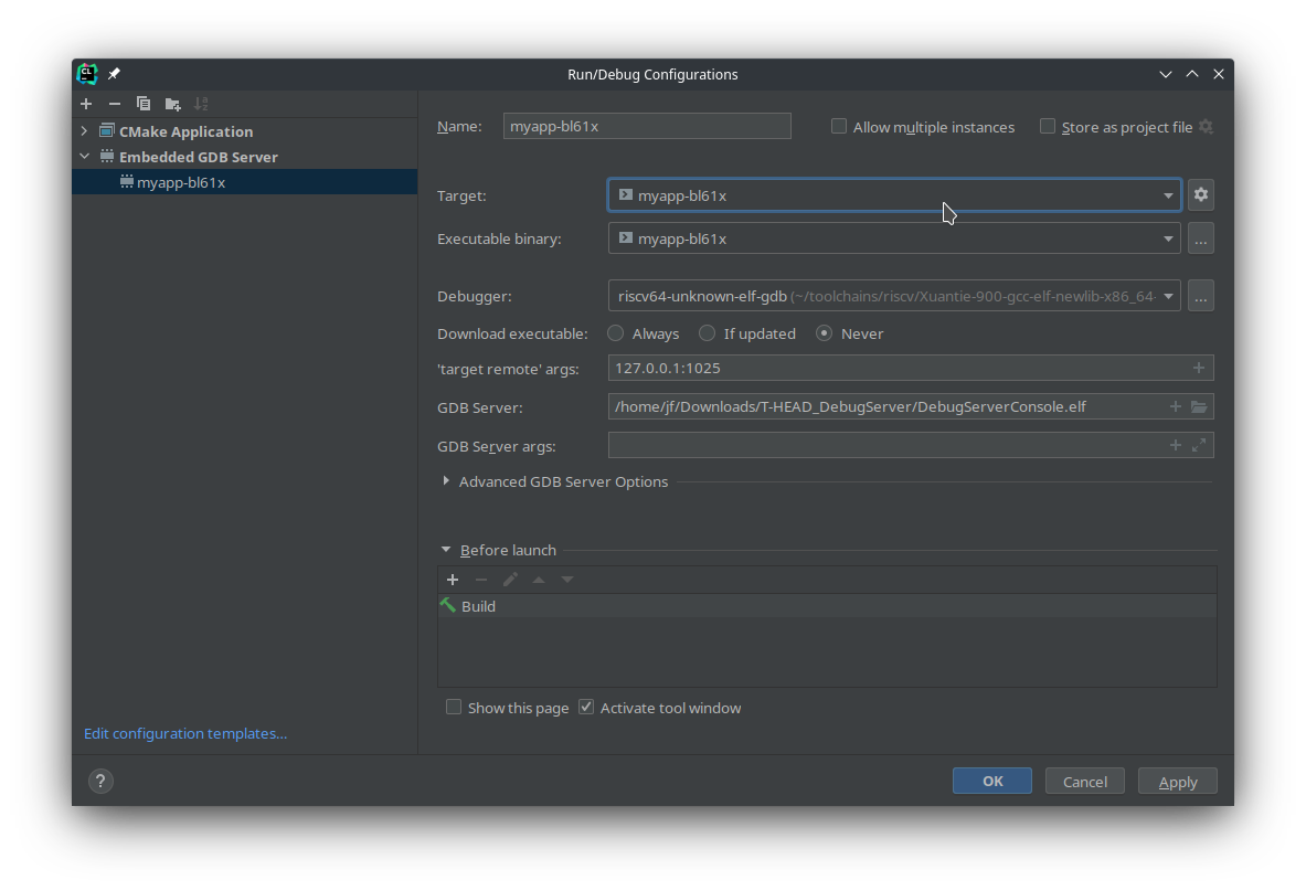
First, create a new Embedded GDB Server configuration:
Then add a new file named .gdbinit to the root of your project with the following content:
set trace-commands on

define bl-reset
set $pc=0xA0000000
set $mie=0
set $mstatus=0x1880
thb main
end

define target hookpost-remote
bl-reset
end

set mem inaccessible-by-default off
set architecture riscv:rv32
set remotetimeout 250

mem 0x42FC0000 0x43010000 rw
mem 0x62FC0000 0x63010000 rw
#rom
mem 0x90000000 0x90020000 ro
#psram
#flash
mem 0xA0000000 0xA0400000 ro
Then hit the Debug button. CLion will automatically start the T-Head DebugServer, then start GDB, connect to the target and configure the session with the parameters from .gdbinit. The hook hookpost-remote will reset the MCU before starting the debugging session.
OpenOCD
OpenOCD is a FOSS tool mainly used for on-chip debugging and in-system programming. It supports many platform (x86, ARM, RISC-V) and many debugging probes.
Bouffalo has recently published the configuration file needed to use OpenOCD to connect to the board, and then GDB to debug the firmware.
I tested the following procedure with 2 JTAG adapters:
-
The [Pine64 JTAG adapter](USB JTAG Adapter - PINE STORE )
Hardware setup
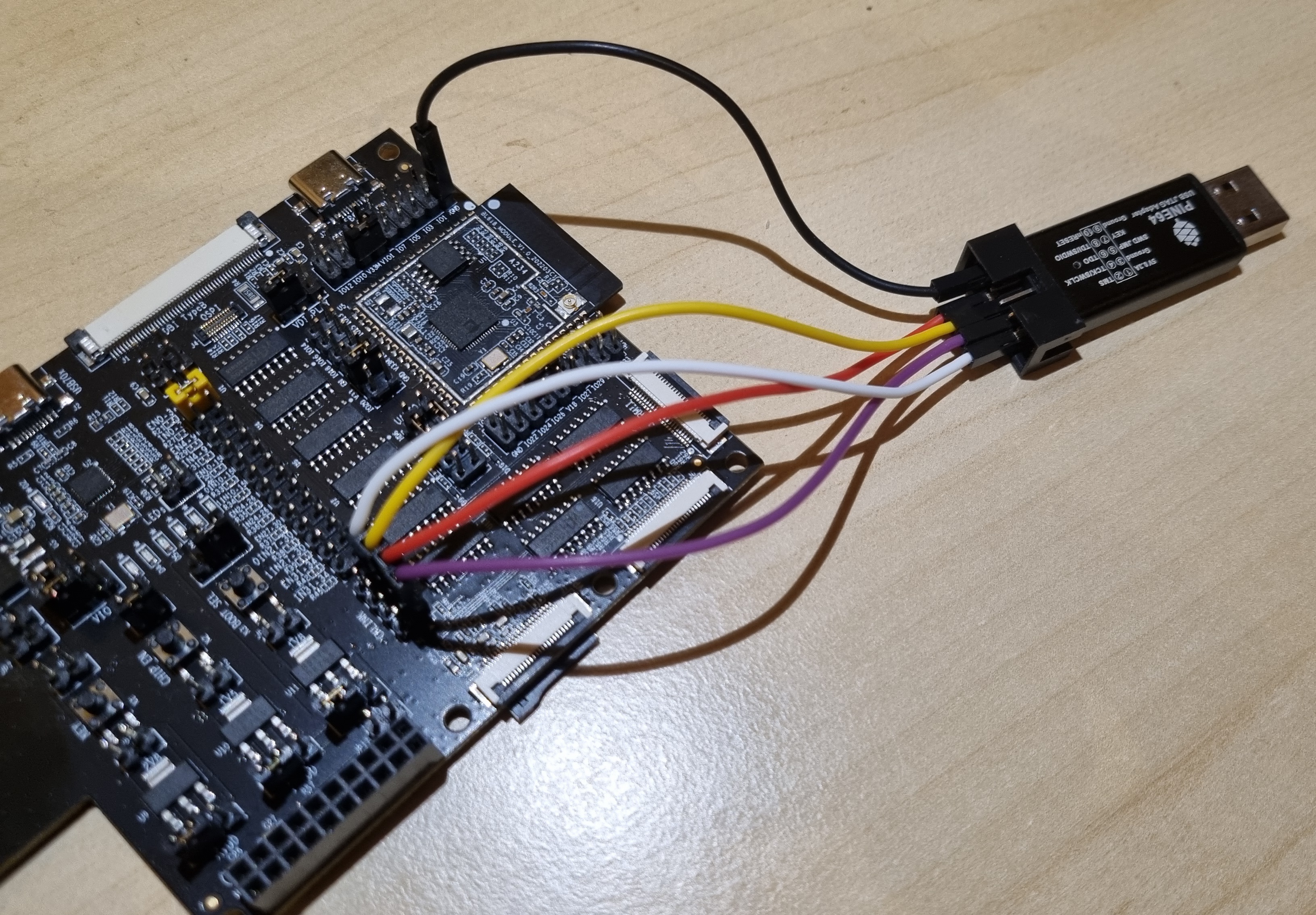
Firt, let’s connect the JTAG adapter to the board : connect the pins TMS, TCK, TDI and TDO of your JTAG adapter to the lefthand pins of J5, and GND from the adapter on any GND pin onboard:
OpenOCD configuration files
You’ll need to provide 2 configuration files to OpenOCD : one that describes your JTAG adapter, and one that specifies the MCU.
Let’s start with the adapter configuration files. Here’s the one for the Pine64 adapter : pine64.conf
interface ftdi
ftdi_vid_pid 0x0403 0x6014

ftdi_channel 0
transport select jtag
adapter_khz     100

ftdi_layout_init 0x00f8 0x00fb
#ftdi_layout_signal nTRST -data 0x0400
#ftdi_layout_signal nSRST -ndata 0x0020

#reset_config srst_only srst_push_pull
#adapter_nsrst_delay 100
#adapter_nsrst_assert_width 100
And here’s the one for the Sipeed adapter : sipeed.cfg
# OpenOCD Script for PineCone connected via Sipeed JTAG Debugger (FTDI FT2232D)
# Ref: bl_iot_sdk/tools/debug/if_bflb_link.cfg
# source [find interface/if_bflb_link.cfg]

# Uncomment to enable debug messages
# debug_level 4

# BouffaloLab USB-JTAG/TTL adapter
# Or Sipeed JTAG Debugger based on FTDI FT2232D

adapter driver ftdi
ftdi_vid_pid 0x0403 0x6010

# Sipeed JTAG Debugger uses FTDI Channel 0, not 1
ftdi_channel 0
# Previously: ftdi_channel 1

transport select jtag
# TODO: Increase the adapter speed (now 100 kHz)
adapter speed 100
# Previously: adapter speed 2000

ftdi_layout_init 0x00f8 0x00fb
And last but not least : the configuration file for the E907 (the RISC-V core inside the BL618) from bl_mcu_sdk
: tgt-e907.cfg
#target chip

set _CHIPNAME riscv
jtag newtap $_CHIPNAME cpu -irlen 5 -expected-id 0x10000b6f

set _TARGETNAME $_CHIPNAME.cpu
target create $_TARGETNAME.0 riscv -chain-position $_TARGETNAME
$_TARGETNAME.0 configure -work-area-phys 0x40000000 -work-area-size 0x10000 -work-area-backup 0
#$_TARGETNAME.0 configure -rtos auto

echo "Ready for Remote Connections"

$_TARGETNAME.0 configure -event reset-assert-pre {
    echo "reset-assert-pre"
    adapter speed 100
}

$_TARGETNAME.0 configure -event reset-deassert-post {
    echo "reset-deassert-post"
    adapter speed 4000
    reg mstatus 0x7800
    reg mie 0x0
#    reg pc 0x22008000
}

$_TARGETNAME.0 configure -event reset-init {
    echo "reset-init"
# 4MHz for FPGA
    adapter speed 4000
}

gdb_memory_map enable
gdb_flash_program disable

riscv set_prefer_sba off
riscv set_command_timeout_sec 3

init
#reset init

#jtag arp_init

#resume
#exit
Debug with OpenOCD and GDB (CLI)
First, run OpenOCD and provide the configuration file corresponding to your configuration (replace pine64.cfg by sipeed.cfg if needed):
openocd  -f pine64.conf -f tgt-e907.cfg
Open On-Chip Debugger 0.11.0-rc2+dev-01539-g50a5971be (2021-03-15-20:23)
Licensed under GNU GPL v2
For bug reports, read
        http://openocd.org/doc/doxygen/bugs.html
DEPRECATED! use 'adapter driver' not 'interface'
DEPRECATED! use 'adapter speed' not 'adapter_khz'
Ready for Remote Connections
Warn : `riscv set_prefer_sba` is deprecated. Please use `riscv set_mem_access` instead.
Info : clock speed 4000 kHz
Info : JTAG tap: riscv.cpu tap/device found: 0x10000b6f (mfg: 0x5b7 (<unknown>), part: 0x0000, ver: 0x1)
Info : datacount=1 progbufsize=2
Info : Examined RISC-V core; found 1 harts
Info :  hart 0: XLEN=32, misa=0x40909125
Info : starting gdb server for riscv.cpu.0 on 3333
Info : Listening on port 3333 for gdb connections
Info : Listening on port 6666 for tcl connections
Info : Listening on port 4444 for telnet connections
Now, you can start and use GDB exactly the same way than explain above in the CKLink section .
Debug with OpenOCD and GDB (CLion)
You can also use OpenOCD with CLion. You simply need to create a new Run/Debug configuration:
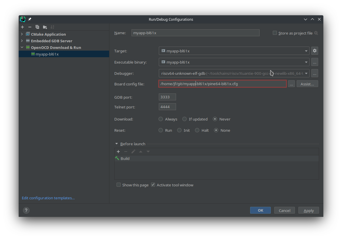
Unfortuntaly, CLion only accepts 1 configuration file, so I merged both the interface and target configuration files in a single one (pine64-bl61x.cfg).
Then, you can create the file .gdbinit as explained in the CKLink section
and start your debugging session by pressing the Debug button.